Section 120-0010
Transmission - Transmission and Mounting
SM 1965 4-00
2
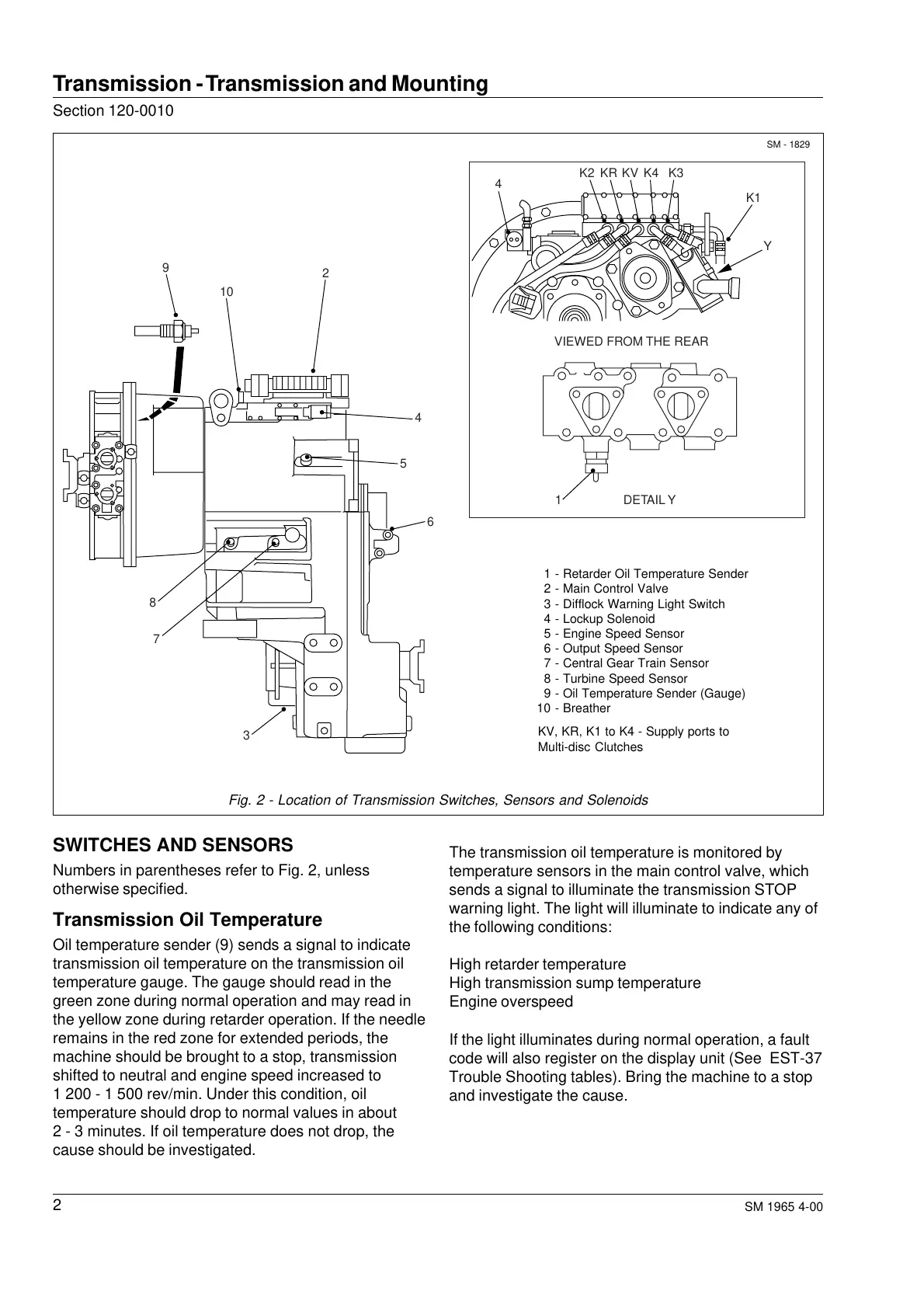
Fig. 2 - Location of Transmission Switches, Sensors and Solenoids
SM - 1829
SWITCHES AND SENSORS
Numbers in parentheses refer to Fig. 2, unless
otherwise specified.
Transmission Oil Temperature
Oil temperature sender (9) sends a signal to indicate
transmission oil temperature on the transmission oil
temperature gauge. The gauge should read in the
green zone during normal operation and may read in
the yellow zone during retarder operation. If the needle
remains in the red zone for extended periods, the
machine should be brought to a stop, transmission
shifted to neutral and engine speed increased to
1 200 - 1 500 rev/min. Under this condition, oil
temperature should drop to normal values in about
2 - 3 minutes. If oil temperature does not drop, the
cause should be investigated.
The transmission oil temperature is monitored by
temperature sensors in the main control valve, which
sends a signal to illuminate the transmission STOP
warning light. The light will illuminate to indicate any of
the following conditions:
High retarder temperature
High transmission sump temperature
Engine overspeed
If the light illuminates during normal operation, a fault
code will also register on the display unit (See EST-37
Trouble Shooting tables). Bring the machine to a stop
and investigate the cause.
4
1
K2 KR KV K4 K3
K1
Y
9
10
2
4
5
6
8
3
7
VIEWED FROM THE REAR
DETAIL Y
1 - Retarder Oil Temperature Sender
2 - Main Control Valve
3 - Difflock Warning Light Switch
4 - Lockup Solenoid
5 - Engine Speed Sensor
6 - Output Speed Sensor
7 - Central Gear Train Sensor
8 - Turbine Speed Sensor
9 - Oil Temperature Sender (Gauge)
10 - Breather
KV, KR, K1 to K4 - Supply ports to
Multi-disc Clutches
Courtesy of Machine.Market