12
02/2021 - EN
If a pellet stove in the “Hermetic” series is installed,
alternatively it is possible to:
- channel the combustion air using a coaxial
exhaustpipefortheexpulsionoftheuegases
and air withdrawal; therefore it is not necessary
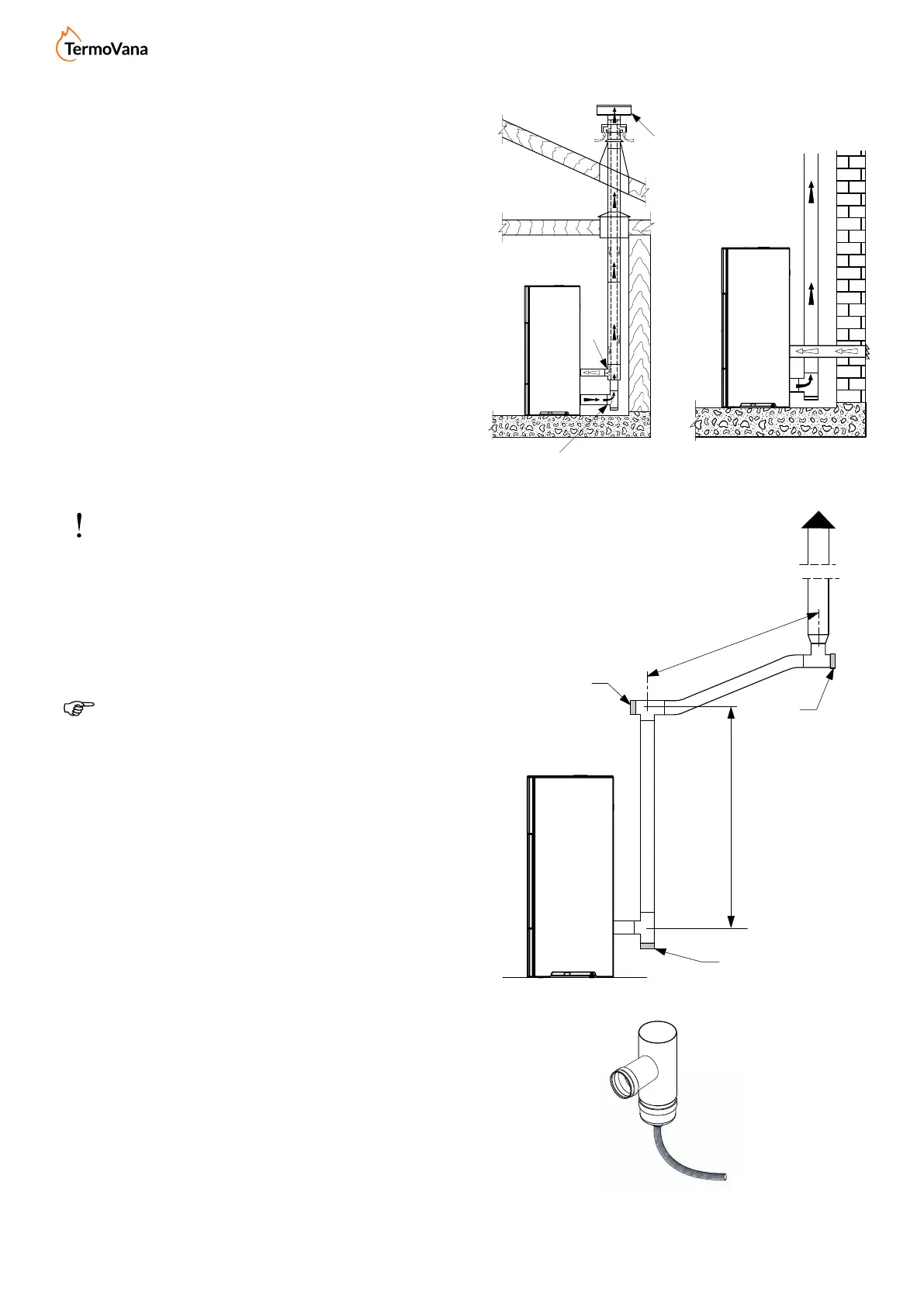
tocreateaclassicairintakeintheroom(g.
5.5 A,B = Air inlet C,D = Flue gas outlet);
- connectthestove’scombustibleairinlettothe
airintakewithasuitableduct(g.5.6).
5.5 FLUE GAS EXHAUST PIPE
The stove works with the combustion chamber in a
vacuum,thereforeitisessentialtoensuretheue
gas exhaust pipe is properly sealed.
The stove must be connected to its own dedicated
flue system, suitable in ensuring the proper
dispersion of the combustion products in the
atmosphere.
Thecomponents that make up theue system
mustbedeclaredsuitableforthespecicoperating
conditions and provided with CE marking.
Itismandatorytocreatearstverticalsectionofa
minimum 1.5 meters to guarantee correct expulsion
oftheuegases.
It is advisable to make a maximum of 3 changes
of direction, in addition to that resulting from the
rear connection of the stove to the chimney, using
45-90°bendsorT-ttings(g.5.7).
Always use a T-tting with an inspectioncap at
each horizontal and verticalvariation of theue
gas exhaust pipe.
OntherstT,attheexitoftheuegasoutletof
the stove, it is necessary to connect a pipe at the
bottom in order to evacuate any condensate that
may form in the chimney (Fig. 5.7a).
The horizontal sections must have a maximum
lengthof2-3mwithanupwardslopeof3-5%(g.
5.7).
Anchor the pipes with suitable collars to the wall.
TheuegasexhaustconnectionMUSTNOTbe
connected:
- to a chimney used by other generators (boilers,
stoves,replaces,etc.);
- to air extraction systems (hoods, vents, etc.)
even if “intubated”.
Itisforbiddentoinstallshut-oanddraughtvalves.
The exhaust of the combustion products must be
provided on the roof.
Fig. 5.7a
Fig. 5.7
Fig. 5.5 Fig. 5.6
B
B
B
MAX 2 - 3 m
C > 3 - 5%
min 1,5 m
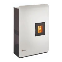
Product images are purely indicative


 To Next Page