EasyManua.ls Logo

Terra MHD001 - User Manual

Terra MHD001
12 pages
Print Icon
To Next Page IconTo Next Page
Loading...
1
HDMI MODULATORS MHD001, MHD001P, MHD002, MHD002P
Vers. 1.06
EN RU
IT
EN
Figure 1. External view of the modulator
1 - HDMI input connector
2 - HDMI output connector (MHD002, MHD002P)
3 - DC IN - DC entry 3.5/1.3 mm (DC jack)
4 - RF IN - RF signal input connector (F type)
5 - RF OUT - RF signal output connector (F type)
PRODUCT DESСRIPTION
The modulators MHD001, MHD001P, MHD002, MHD002P are intended to encode HDMI video and audio signal to DVB-T
signal and modulate it in VHF and UHF ranges. The modulators MHD002, MHD002P have HDMI loop through output.
MHD001P and MHD002P are packed with external mains power supply.
The modulators are intended for indoor use only.
SAFETY INSTRUCTIONS
Installation of the modulator must be done according IEC60728-11 and national safety standards.
The modulator is powered from external power supply +12 V. This voltage is not dangerous to life.
Any repairs must be done by a qualied personnel.
To avoid the electric shock follow these instructions:
Do not plug mains power supply of the modulator into the mains until all cables have been connected correctly;
To disconnect the modulator from mains completely, disconnect plug of modulator power supply from mains socket;
Modulator shall not be exposed to dripping or splashing water and no objects lled with liquids, such as vases, shall be
placed on it;
Avoid placing modulator next to central heating components, near highly compustible materials and in areas of high humidity;
Before connecting the modulator to multimedia system, be sure that system is installed in accordance to national safety
standards;
Devices of multimedia system should have easy access to disconnect them from the mains supply;
No naked ame sources, such as lighted candles, should be placed on modulator;
If the modulator has been kept in cold conditions for a long time, keep it in a warm room no less than 2 hours before
plugging into the mains;
Do not insert any objects into ventilation openings;
The ventilation should not be impeded by covering the ventilation openings with items, such as newspapers, table-cloths,
curtains;
Mount the modulator on not ammable wall or in not ammable installation box in vertical position with RF connectors
underneath. The modulator must be xed with steel screws Ø 3.5-4 mm. The screws are not included in a package;
From top, front and bottom of installed modulator must be at least 10 cm free space.
EXTERNAL VIEW
6 - two-digit LED display
7 - DC voltage indicator
8 - exterior lid (open by hand)
9 - setting mode indicator
10 - HDMI signal presence indicator
2. 1.
2
1
8
7
6
3 4 5
9
10
Manual:
Question and Answer IconNeed help?

Do you have a question about the Terra MHD001 and is the answer not in the manual?

Overview

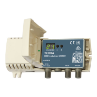
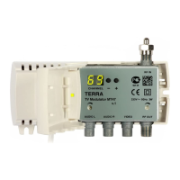
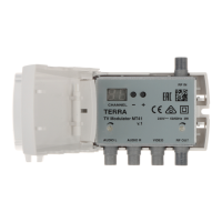
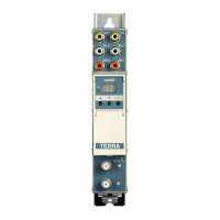
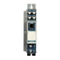
This document describes the HDMI Modulators MHD001, MHD001P, MHD002, MHD002P, devices designed to encode HDMI video and audio signals into DVB-T digital television format and modulate them in VHF and UHF ranges. The MHD002 modulators are equipped with an HDMI loop-through output, while the MHD001P and MHD002P models also feature an external mains power supply. These modulators are intended for indoor use only.

Function Description

The primary function of these modulators is to convert HDMI input signals into DVB-T compatible RF output signals. This allows HDMI sources to be distributed over a coaxial cable network to multiple televisions that can tune into DVB-T channels.

MHD001 and MHD001P: These models are designed for HDMI video input resolution up to 1920x1080p60. MHD002 and MHD002P: These models also support HDMI video input resolution up to 1920x1080p60 and feature an HDMI loop-through output, allowing the HDMI signal to be passed through to another display device without interruption.

All models utilize H.264 encoding (MPEG-4 AVC/H.264, Baseline profile 4.0) for video and MPEG-1 Layer II, AAC for audio. The transport stream processing is automatic generation, supporting PAT, SDT, and PMT tables. The RF output is DVB-T standard, with a frequency range of 174-230 MHz (VHF) and 470-862 MHz (UHF). The MER (Modulation Error Ratio) is typically 32 dB, and the modulation type is QAM64. The channel bandwidth is 7 MHz or 8 MHz.

Important Technical Specifications

HDMI Video Input Resolution: Up to 1920x1080p60 for all models. H.264 Encoder: MPEG-4 AVC/H.264, Baseline profile 4.0. Audio Encoding: MPEG-1 Layer II, AAC. RF Output Standard: DVB-T. RF Output Frequency Range: 174-230 MHz, 470-862 MHz. MER: Typically 32 dB. Modulation: QAM64. Channel Bandwidth: 7 MHz / 8 MHz. Shoulder Attenuation: > 36 dB. Level/Impedance: 90 dBµV/75 Ω. Output Level Adjustment: 0 to -30 dB by 1 dB step. Loop Through Frequency Range (MHD002/P): 45-862 MHz / ≤ 2.5 dB.

Power Supply:

  • MHD001, MHD002: 12 V ± 1 V, 300 mA current consumption. Power consumption is 4 W.
  • MHD001P, MHD002P: External mains power supply 12 V ± 1 V, 100-240 V~, 50/60 Hz, 4.4 W.
    • Output voltage: +12 V ± 1 V
    • Output current: > 0.3 A
    • Ripple at single and/or double mains frequency: < 10 mV p-p
    • Ripple & noise: < 180 mV p-p
    • Output connector type: 3.5/1.3 (+) plug or 5.5/2.1 mm (+) plug
    • Short circuit protection: Yes
    • Double insulated (marked ⎔)

Operating Temperature: 0°C to +40°C. Dimensions/Weight (packed): 133x63x39 mm / 0.18 kg (with power supply unit - 0.34 kg).

Usage Features

Installation:

  • The modulators are designed for indoor use only.
  • Installation must comply with IEC60728-11 and national safety standards.
  • Power supply for MHD001 and MHD002 is +12V. For MHD001P and MHD002P, an external mains power supply is provided.
  • To avoid electric shock, follow proper grounding procedures.
  • Do not plug the mains power supply into the mains until all cables have been correctly connected.
  • To disconnect the modulator from mains completely, disconnect the plug of the modulator power supply from the mains socket.
  • The modulator should not be exposed to dripping or splashing water, and no objects filled with liquids should be placed on it.
  • Avoid placing the modulator next to central heating apparatus, near highly combustible materials, and in areas of high humidity.
  • Before connecting the modulator to a multimedia system, ensure that the system is installed in accordance with national safety standards.
  • Devices of a multimedia system should have easy access to disconnect them from the mains supply.
  • No naked flame sources, such as lighted candles, should be placed on the modulator.
  • If the modulator has been kept in cold conditions for a long time, keep it in a warm room no less than 2 hours before plugging into the mains.
  • Do not insert any objects into ventilation openings.
  • The ventilation should not be impeded by covering the ventilation openings with items such as newspapers, table-cloths, curtains.
  • Mount the modulator on a non-flammable wall or in a non-flammable installation box in a vertical position with RF connectors underneath. The modulator must be fixed with sheet screws Ø 3.5-4 mm. The screws are not included in the package.
  • From top, front, and bottom of the installed modulator must be at least 10 cm free space.
  • Do not connect TV antennas to modulator RF IN connector directly. If you intend to combine TV signals of antennas and the modulator, plug in a booster with output-to-input isolation ≥20 dB between the antenna output and RF IN connector.

Configuration: The modulator has two modes of operating:

  1. Normal: After power-on.
  2. Setting: To enter the setting mode, press "+" and "-" buttons simultaneously. The text setting mode press "+" and "-" buttons simultaneously for 1 second. The setting mode is indicated by a point after the last digit.

Default Settings:

  • Output channel 21: Protection from unauthorized access OFF (Preset oF).
  • Service name MHD001 CH_21: (Preset OO).
  • Output signal attenuator 15 dB: (Preset I5).
  • Output signal ON: (Preset oN).
  • Region Europe: (Preset EU).

Changing Settings:

  • Output Channel: Can be selected in normal mode by pressing buttons "+" or "-" (see tables 2-6 for channel assignments).
  • Service Number: Press "+" button (displayed n.O); press "+" button again (displayed number from 00 to 99). When the service number is set to a number greater than 00, the logical channel number will be added and the service name will be set to MHD001 CH_service number. For New Zealand region, service name is set according to Table 7.
  • Output Attenuator: Press "+" button (displayed A.t); press "+" button again (displayed number from 00 to 30).
  • Output Signal Switching: Press "+" button (displayed r.F); press "+" button again (displayed o.n or o.F).
  • Region Switching: Press "+" button (displayed r.S); press "+" button again (displayed region name (see Table 1)).
  • Software Version: Press "+" button (displayed v.E); press "+" button again (displayed software version of the modulator).

Reset to Default Settings Procedure:

  1. Disconnect the modulator from the power supply.
  2. Press and hold the "-" button.
  3. Connect the modulator to the power supply.
  4. Release the "-" button. After this procedure, all settings, except the region, will be set to default values.

Maintenance Features

  • The device is designed for long-term reliable operation with minimal maintenance.
  • Regular cleaning of the exterior surfaces with a soft, dry cloth is recommended.
  • Ensure that ventilation openings are not blocked to prevent overheating.
  • Avoid exposure to extreme temperatures, humidity, or direct sunlight.
  • In case of malfunction, refer to the troubleshooting section of the manual or contact qualified personnel.
  • Do not attempt to open or repair the device yourself, as this may void the warranty and pose a safety risk.
  • The product is compliant with relevant clauses of the European Directive 2002/96/EC. The unit must be recycled or discarded according to applicable local and national regulations (marked on the rear side).
  • The product is intended for indoor usage only (marked on the rear side).
  • The product is in accordance with following standards: EU: EMC norm EN50083-2, safety norm EN52368-1 and RoHS norm EN50581.
  • This product is in accordance with Custom Union Technical Regulations: "Electromagnetic compatibility of technical equipment" CU TR 020/2011, "On safety of low-voltage equipment" CU TR 004/2011.
  • This product is in accordance with safety standard AS/NZS 60065 and EMC standards for Australia.

The product comes with a 12-month warranty from the date of purchase.

Terra MHD001 Specifications

General IconGeneral
BrandTerra
ModelMHD001
CategoryModulator
LanguageEnglish

Related product manuals