Twin TV modulators mt420, mt420C
Product description
The mt420, mt420C are frequency agile vestigial side band (VSB) modulators intended to generate signals of two TV
channels in CATV frequency range from 110 MHz up to 862 MHz.
There are incorporated two fully independent TV modulators in one unit. The mt420 creates signals according to
B/G/D/K/I/L/Au standards, mt420C - B/G/D/K/Au stereo A2 standards.
The modulators could be used as stand-alone unit as well as modular system powered from single power supply.
The modulators are intended for indoor use only.
Safety instructions
Installation of the modulators must be done according IEC60728-11 and national safety standards.
The modulators are powered from power supply unit (PSU) +12 V. This voltage is not dangerous to life.
PSU +12 V must have a short circuit protection.
Any repairs must be done by a qualied personnel.
Do not plug the PSU +12 V into the mains socket until all modules cables have been connected correctly.
The mains socket of PSU +12 V must be easily accessible.
To disconnect the modulators power completely, disconnect the PSU +12 V from the mains.
The modulators shall not be exposed to dripping or splashing water and no objects lled with liquids, such as vases, shall
be placed on it.
Avoid placing modulators next to central heating components and in areas of high humidity.
No naked ame sources, such as lighted candles, should be placed on modulators.
If the modulators have been kept in cold conditions for a long time, keep it in a warm room no less than 2 hours before
plugging into the mains.
The ventilation should not be impeded by covering the ventilation openings with items, such as newspapers, table-cloths,
curtains.
Mount the modulators in vertical position. From top, front and bottom of installed modulators must be at least 10 cm free
space.
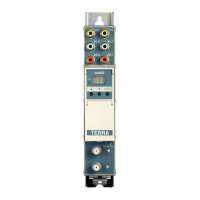
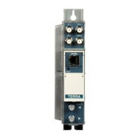
External view
1 - V.1 - video signal input section 1 (RCA socket)
2 - AL.1 - audio left channel sound section 1 (RCA socket)
3 - AR.1 - audio right channel sound section 1 (RCA socket)
4 - ◄ - RF input (output signal loop-through) (F socket)
5 - ► - RF output (F socket)
6 - two digit LED display
7 - V.2 - video signal input section 2 (RCA socket)
8 - AL.2 - audio left channel sound section 2 (RCA socket)
9- AR.2 - audio right channel sound section 2 (RCA socket)
10 - indicator of hyperband channels
11 - +12 V powering input (screw terminal)
12 - power distribution bus connector (under the cover)
Figure 1. External view of the modulator
Draugystes str. 22, LT-51256 Kaunas, Lithuania, tel.: +370 37
-
31 34 44, fax: +370 37
-
31 35 55
E-mail: sales@terraelectronics.com, http://www.terraelectronics.com
SYSTEM: B, Australia
Band Channel Displayed Vision C. Audio C.
IV 20 20 471.25 476.75
21 21 478.25 483.75
22 22 485.25 490.75
23 23 492.25 497.75
24 24 499.25 504.75
25 25 506.25 511.75
26 26 513.25 518.75
27 27 520.25 525.75
28 28 527.25 532.75
29 29 534.25 539.75
30 30 541.25 546.75
31 31 548.25 553.75
32 32 555.25 560.75
33 33 562.25 567.75
34 34 569.25 574.75
35 35 576.25 581.75
V 36 36 583.25 588.75
37 37 590.25 595.75
38 38 597.25 602.75
39 39 604.25 609.75
40 40 611.25 616.75
41 41 618.25 623.75
42 42 625.25 630.75
43 43 632.25 637.75
44 44 639.25 644.75
45 45 646.25 651.75
46 46 653.25 658.75
47 47 660.25 665.75
48 48 667.25 672.75
49 49 674.25 679.75
50 50 681.25 686.75
51 51 688.25 693.75
52 52 695.25 700.75
53 53 702.25 707.75
54 54 709.25 714.75
55 55 716.25 721.75
56 56 723.25 728.75
57 57 730.25 735.75
58 58 737.25 742.75
59 59 744.25 749.75
60 60 751.25 756.75
61 61 758.25 763.75
62 62 765.25 770.75
63 63 772.25 777.75
64 64 779.25 784.75
65 65 786.25 791.75
66 66 793.25 798.75
67 67 800.25 805.75
68 68 807.25 812.75
69 69 814.25 819.75
70 70 821.25 826.75
71 71 828.25 833.75
72 72 835.25 840.75
73 73 842.25 847.75
74 74 849.25 854.75
75 75 856.25 861.75
Table 7
SYSTEMS: I, G, H, K, L
Band Channel Vision C. Audio C. Audio C. Audio C.
Stand.G,H Stand.I Stand.K,L
IV 21 471.25 476.75 477.25 477.75
22 479.25 484.75 485.25 485.75
23 487.25 492.75 493.25 493.75
24 495.25 500.75 501.25 501.75
25 503.25 508.75 509.25 509.75
26 511.25 516.75 517.25 517.75
27 519.25 524.75 525.25 525.75
28 527.25 532.75 533.25 533.75
29 535.25 540.75 541.25 541.75
30 543.25 548.75 549.25 549.75
31 551.25 556.75 557.25 557.75
32 559.25 564.75 565.25 565.75
33 567.25 572.75 573.25 573.75
34 575.25 580.75 581.25 581.75
35 583.25 588.75 589.25 589.75
36 591.25 596.75 597.25 597.75
37 599.25 604.75 605.25 605.75
V 38 607.25 612.75 613.25 613.75
39 615.25 620.75 621.25 621.75
40 623.25 628.75 629.25 629.75
41 631.25 636.75 637.25 637.75
42 639.25 644.75 645.25 645.75
43 647.25 652.75 653.25 653.75
44 655.25 660.75 661.25 661.75
45 663.25 668.75 669.25 669.75
46 671.25 676.75 677.25 677.75
47 679.25 684.75 685.25 685.75
48 687.25 692.75 693.25 693.75
49 695.25 700.75 701.25 701.75
50 703.25 708.75 709.25 709.75
51 711.25 716.75 717.25 717.75
52 719.25 724.75 725.25 725.75
53 727.25 732.75 733.25 733.75
54 735.25 740.75 741.25 741.75
55 743.25 748.75 749.25 749.75
56 751.25 756.75 757.25 757.75
57 759.25 764.75 765.25 765.75
58 767.25 772.75 773.25 773.75
59 775.25 780.75 781.25 781.75
60 783.25 788.75 789.25 789.75
61 791.25 796.75 797.25 797.75
62 799.25 804.75 805.25 805.75
63 807.25 812.75 813.25 813.75
64 815.25 820.75 821.25 821.75
65 823.25 828.75 829.25 829.75
66 831.25 836.75 837.25 837.75
67 839.25 844.75 845.25 845.75
68 847.25 852.75 853.25 853.75
69 855.25 860.75 861.25 861.75
Table 8
Table 9
Displayed Shift
MHz
0 0
1 +0.25
2 +0.5
3 +0.75
4 +1.0
5 +1.25
6 +1.5
7 +1.75
8 +2.00
9 +2.25
-9 -2.25
-8 -2.00
-7 -1.75
-6 -1.5
-5 -1.25
-4 -1.0
-3 -0.75
-2 -0.5
-1 -0.25
FINE TUNING / ПЛАВНОЕ ИЗМЕНЕНИЕ/
REGOLAZIONE FINE
UHF BAND IV AND BAND V CHANNELS / КАНАЛЫ IV И V ДМВ ДИАПАЗОНОВ /
CANALI BANDA UHF, BANDA IV E BANDA V
Multichannel headend
Vers. 1.03