15
III. FRONT PANEL
3.1 Introduction
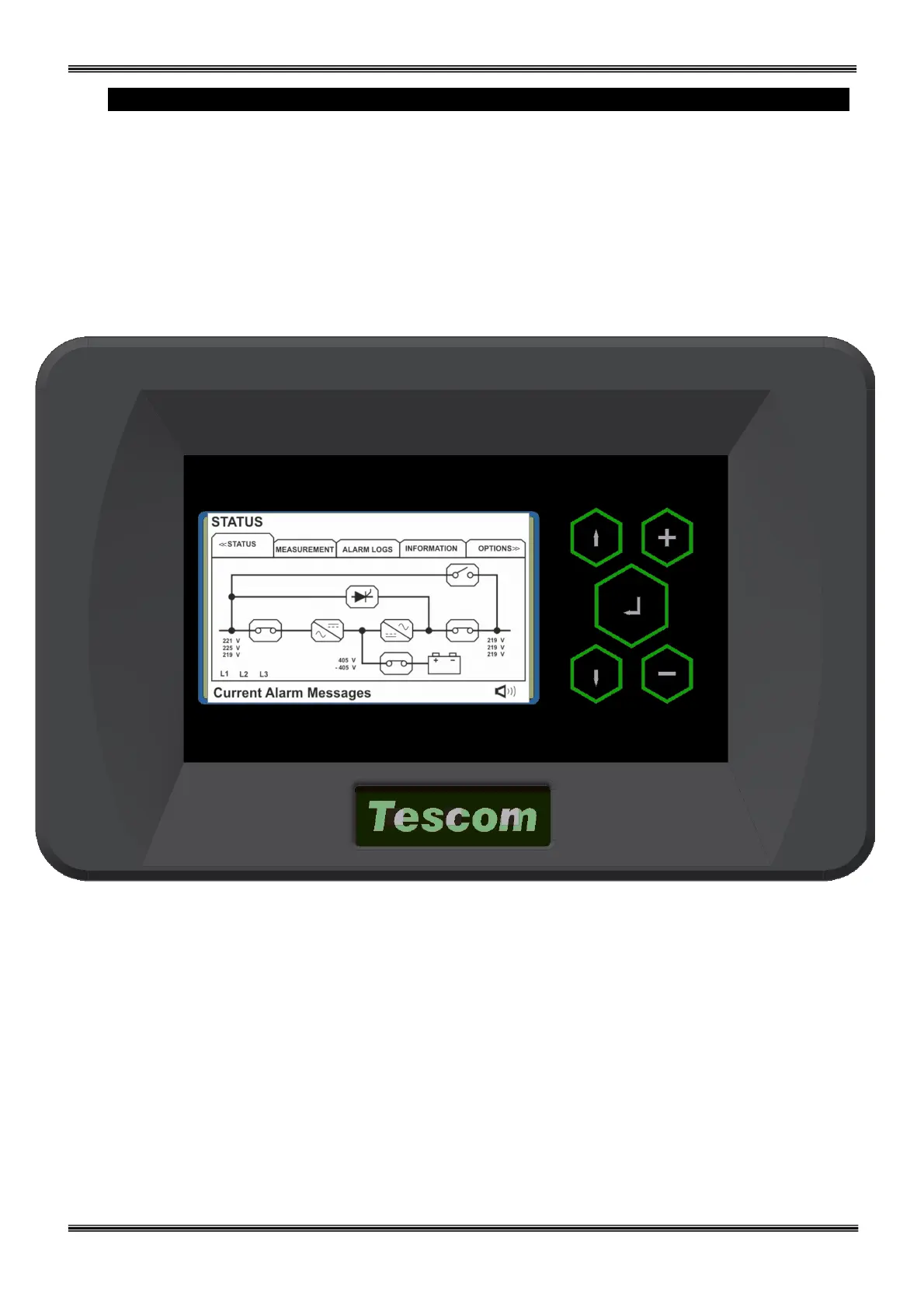
The front panel of UPS, consisting of a high resolution TFT screen together with 5 function keys, allows
the complete monitoring of the UPS status including all measurements related to UPS operation. The mimic
flow diagram helps to comprehend the operating status of the UPS. By using the function keys the operator
can move on menus and change some parameters. Touch-screen operation is also possible.
Figure 3.1 Control panel oft he UPS
L1
:
Maintenance bypass switch
L2
:
Load on bypass indicator lamp
L3
:
Input voltage indicator lamp
L4
:
Rectifier run pilot lamp
L5
:
Battery operation indicator lamp
L6
:
Load on UPS indicator lamp
L7
:
Output switch on indicator lamp
There are 5 control buttons on the UPS Front panel ,ENTER button provides selection decleration,up and
down buttons provides to surf on menus, (+) and (-) buttons are used for adjustments or option selection.