1.9 Square Wave Adjustment
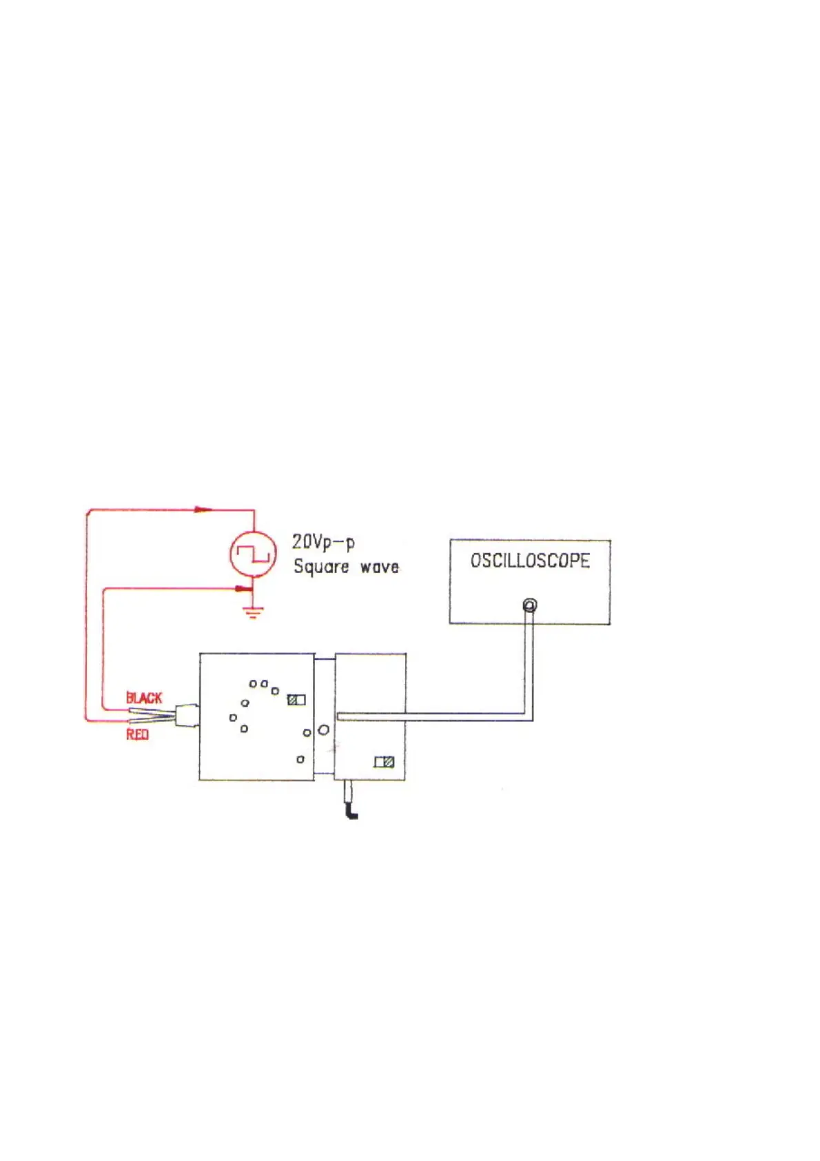
a. Referring to Fig. 10, connect output BNC to the oscilloscope has good grounding.
b. Connect the red input line to a 20Vp-p, 10KHz square wave signal source and the black input line to
ground.
c. Put SW1 at 1/10 (or 1/20).
d. Set the VOLTS/DIV switch on oscilloscope’s panel to o.1V for 1/10 (or 1/20) attenuation and the
TIME/DIV switch to 20us.
e. Adjust VC1 to make the displayed waveform become as Fig 11(b).
f. Connect the black input line to 20Vp-p, 10KHz square wave signal source and the red input line to
ground.
g. Adjust VC2 to make the displayed waveform become as Fig. 11(b).
Fig. 10
6