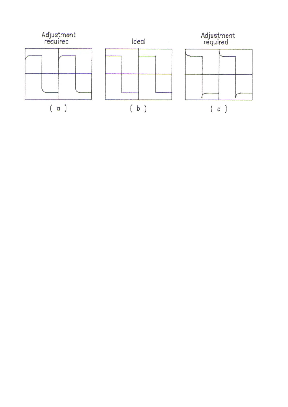
Fig. 11
1.10 Repeat 3.2 and 3.3 adjustment until both adjustments are O.K.
1.11 High Frequency CMRR adjustment
a. Referring to Fig. 12, connect output BNC to the oscilloscope has good grounding.
b. Connect both input lines to a 155Vp-p, 20KHz, sine wave signal source.
c. Put SW1 at 1/10 (1/20).
d. Set VOLTS/DIV switch on oscilloscope’s panel to 1mV and the TIME/DIV switch to 0.1ms.
e. Adjust VC1 slightly to make the amplitude of displayed waveform as small as possible. Finally the
amplitude should be less than 2mV.
7