Do you have a question about the Testec SI-9001 and is the answer not in the manual?
Explains components like switches, resistors, and capacitors used in calibration.
Outlines initial steps including power connection and warm-up before calibration.
Guides on adjusting output voltage to zero using VR2 and VR4 at different attenuation settings.
Explains how to adjust VR1 to minimize waveform amplitude using an oscilloscope.
Guides on using VC1 and VC2 to achieve ideal square wave display on an oscilloscope.
Instructs on adjusting VC1 to minimize waveform amplitude using a sine wave signal.
Details using VR3 to set the output voltage to a specific value with a DC voltage source.
This document outlines the calibration procedures for the TT-SI 9001 and TT-SI 9002 devices, focusing on offset, low frequency CMRR, square wave, high frequency CMRR, and accuracy adjustments. The guide begins by detailing the various adjustment points on the device, providing a clear explanation of each component's function.
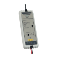
The TT-SI 9001 and TT-SI 9002 are devices that require precise calibration to ensure accurate measurements. The calibration process involves adjusting several internal components, including variable resistors and capacitors, to achieve optimal performance. The device features a switch (SW1) for selecting attenuation ratios, allowing for different measurement ranges. A power switch (SW2) controls the device's operation, and an LED indicator confirms that the unit is powered on.
Key adjustment points and their functions are:
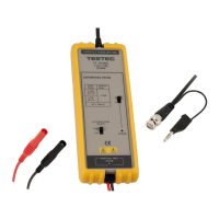
The device is designed for use with external measurement equipment such as a Digital Multimeter (DMM) and an oscilloscope. The input lines (black and red) are used to connect to the signal source, while the BNC connector output is used to connect to the DMM or oscilloscope.
To begin using the device, a 6VDC power adapter must be connected to CON1. Once powered on, the LED indicator should light up. It is recommended to warm up the unit for 10 minutes before starting any calibration procedures to ensure stable operation.
The calibration process involves several steps, each requiring specific connections and adjustments:
The manual provides detailed instructions on how to open the device's case for maintenance and calibration. This involves a series of steps to carefully disassemble the unit without causing damage.
These instructions ensure that the device can be safely opened to access the internal components for calibration and any necessary repairs or maintenance. The clear diagrams accompanying the text further aid in understanding the disassembly process. The emphasis on careful handling during disassembly highlights the precision required for maintaining the device's integrity.
| Connector | BNC |
|---|---|
| Operating Temperature | 0°C to +50°C |
| Bandwidth | DC - 100 MHz |
| Rise Time | ≤ 3.5 ns |
| Storage Temperature | +70°C |