66.. CCoonnnneeccttiinngg pprroobbeess
13
Observe the following points when connecting the probes to the
data logger and to the measurement points:
Observe poles of plug.
Insert the plugs firmly into the connections to guarantee that
they are properly in place. Force should not be used.
Ensure that the plugs are firmly attached to the data logger or
that the connections are in place with a blind plug.
Ensure that the probe is positioned properly to avoid disturbing
influences on the measurement.
testo 175-T3
:
Ensure that each respective configured probe is connected to
the socket (via testo ComSoft software). The numbers of the
connections are printed on the housing!
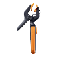
testo 175-S1/S2
:
The testo 175-S1/S2 data logger is designed for use in electric
circuits in measurement technology, automatic control, information
technology in process, laboratory and technical systems (0 to
20mA current loop; 0-1V, 0-10V voltage sockets).
Connect the cables by following the printed connection plan.
Warning!
Strong currents and high voltage!
Electric sshock!
The
testo 175-S1 and testo 175-S2 data logger should only be connected to electric
circuits from the SELV (safety extra-low voltage) or PELV (protective extra-low voltage)
category.
The testo 175-S1 and testo 175-S2 data logger should only be connected to direct
current circuits.Rated voltage should only be max. 60 V DC.
The electric circuits in the data logger should only be set up, connected, operated
and maintained by trained personnel.
Disconnect the measurement leads from the logger before changing the battery.