Do you have a question about the TESTO 750 and is the answer not in the manual?
Read manual carefully, keep document handy, and forward to subsequent users for safe operation.
Use by trained personnel, precautions for voltages >120V DC/50V AC, grip areas, battery leakage handling.
Permitted for voltage testing, field detection, phase testing, continuity; not for explosive atmospheres or rain.
Details voltage ranges, display values, tolerances, frequency, and load characteristics.
Covers voltage range, frequency, and display for single-pole phase detection.
Specifies voltage range, frequency, and LED display for determining rotary field direction.
Outlines resistance range, tolerances, test current, signaling, and overvoltage protection.
Includes operating/storage temperatures, humidity, altitude, measurement category, protection class, and power.
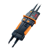
Identifies probe tips, illumination, LED display, and explains display symbols for AC, DC, L/R, Rx, voltage values.
Details the meaning of various icons including warnings, safety symbols, CE mark, and WEEE compliance.
Instructions on how to power on the instrument by connecting probes or pressing buttons.
How to switch the white LED measuring point illumination on/off on testo 750-2/-3.
Ensures instrument condition, performs function test, checks operation, and secures against unintentional use.
Connect probes, automatic power-on, LED indicators for voltage, acoustic signal for safety extra-low voltage.
Procedure for testing voltage with RCD/FI trip test using buttons for 10/30mA circuits.
Performing single-pole phase testing from 100V AC, its limitations and when two-pole testing is needed.
Steps for continuity testing, including disconnecting power, voltage check, probe connection, and indicators.
How to determine rotary field direction in three-phase systems using probe tips and grip area.
Procedure for replacing batteries when Rx indicator or battery icon is shown.
General statement that the instrument requires no particular maintenance when operated correctly.
Recommends removing batteries for long-term storage to prevent damage from leaks.
How to clean the instrument using a damp cloth and mild detergent, avoiding harsh cleaners.
Dispose of rechargeable/spent batteries according to legal specifications.
Return product to Testo or use separate collection for electronic devices at end-of-life.
| Continuity Testing | Yes |
|---|---|
| Single Pole Phase Testing | Yes |
| Vibration Alert | Yes |
| Voltage Range | 12 V to 690 V AC/DC |
| Safety Category | CAT IV 600 V |
| Resistance Range | 0 Ω |
| Phase Sequence Testing Voltage Range | 100 V to 690 V AC |
| Operating Temperature | -10 °C to +50 °C |
| Display | Graphical LCD with backlight |