EasyManuals Logo

TESTO 750 User Manual

TESTO 750
12 pages
To Next Page IconTo Next Page
To Previous Page IconTo Previous Page
Page #6 background imageLoading...
Page #6 background image
6 Overview
6
6 Overview
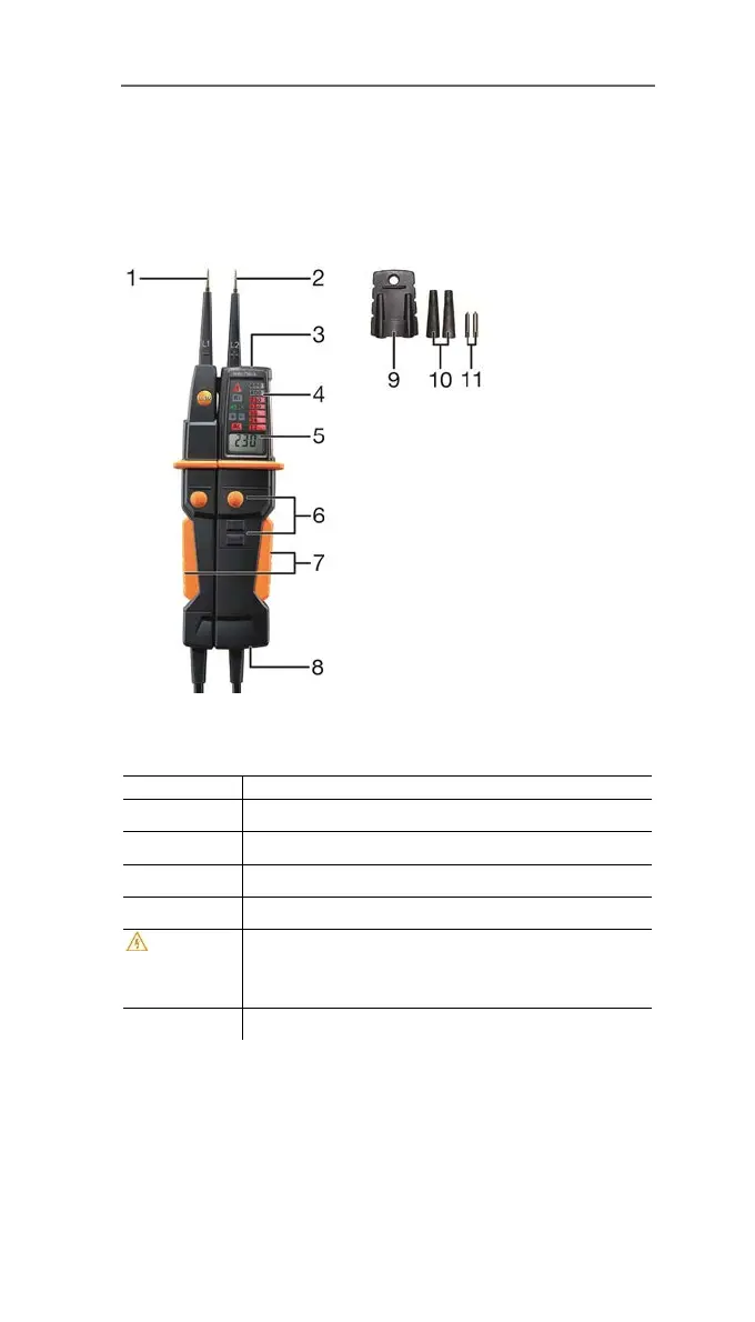
6.1. Display and control elements
Product variant shown: testo 750-3
1 Probe tip - (L1)
2 Probe tip + (L2)
3 Measuring point illumination, white LED (only testo 750-2 and -3)
4 LED display
Display Meaning
AC Voltage testing: AC voltage is applied
+ - Voltage testing: DC voltage is applied
L R Voltage testing AC: rotary field direction left or right
Rx Continuity testing: continuity detected
Safe
ty extra-low voltage exceeded (> 50 V AC /
> 120 V DC)
Single-pole phase testing (only testo 750-2 / -3):
Phase detected
12, 24 etc. Applied voltage value in V
5 LCD display (only testo 750-3)

Questions and Answers:

Question and Answer IconNeed help?

Do you have a question about the TESTO 750 and is the answer not in the manual?

TESTO 750 Specifications

General IconGeneral
Continuity TestingYes
Single Pole Phase TestingYes
Vibration AlertYes
Voltage Range12 V to 690 V AC/DC
Safety CategoryCAT IV 600 V
Resistance Range0 Ω
Phase Sequence Testing Voltage Range100 V to 690 V AC
Operating Temperature-10 °C to +50 °C
DisplayGraphical LCD with backlight

Related product manuals