7 Operating the instrument
7
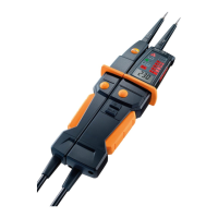
6 Control keys:
Key Function
2x (only testo 750-2 / -3)
Carry out RCD/FI trip test
HOLD (only testo 750-3) Record reading
(only testo 750-2 / -3)
• Switch measuring point illumination
on/off
• Switch LCD display background
illumination on/off (only testo 750-3)
7 Grip area
8 Battery compartment
9 Probe tip protective cap (with storage compartments for probe tip cover
and probe tip extension)
10 GS38 probe tip cover
11 Probe tip extension (diameter 4 mm, screw-on)
6.2. Explanation of icons
Icon Meaning
Cautio
n! Warning about a danger spot, refer to instruction
manual
Cautio
n! Dangerous voltage, risk of electric shock
Continuous double
or reinforced insulation in accordance with
Category II DIN EN 61140
Suitable
for work on live parts
Conformity mark, verifies compliance with the valid EU
Directives: EMC Directive (2014/30/EU) with the standard
EN 61326-1, Low-Voltage Directive (2014/35/EU) with the
standard EN 61010-1
Fulfils applic
able Australian provisions.
The instrument
complies with the WEEE Directive
(2012/19/EU)
7 Operating the instrument
7.1. Switching the instrument on
> Connect both probe tips or press any button.
- The instrument switches on.
On the testo 750-3, the LCD display is switched on and shows ---.