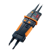
8 Carrying out a test
9
The recorded value will automatically be deleted after approx. 10 seconds
once voltage is no longer being applied to the probe tips. This is indicated
by a short acoustic signal.
Once the recorded value has been deleted, the LCD display once again
indicates the voltage currently being applied to the probe tips.
The LED voltage display always indicates the voltage currently being
applied in the electrical circuit.
Voltages below approx. 10 V AC/DC cannot be recorded, --- is shown on
the LCD display.
8.3. Voltage testing with RCD/FI trip test (only
testo 750-2 / -3)
For voltage tests in systems with RCD/FI residual current circuit breakers,
these can be tested with a 10 mA or 30 mA nominal current by connecting a
load:
> Test the voltage between L and PE and press both buttons at the
same time.
- The RCD/FI should trip.
8.4. Single-pole phase testing
Single-pole phase testing is possible from AC voltages of approx. 100 V.
During the single-pole phase testing to determine external conductors, the
display function may be impaired, for example due to insulating personal
protective equipment or other insulators.
The single-pole phase testing is not suitable for testing for absence of
voltage. Two-pole voltage testing is required for this.
> Connect the voltage tester probe tip + (L2) to the test object.
- is illuminated to signify the phase testing.
8.5. Continuity testing
✓ Disconnect the test circuit/object from the power supply.
✓ Conduct a two-pole voltage test on the test object to confirm the
absence of voltage.
> Connect both probe tips to the test object.
- For continuity up to approx. 500 kΩ, Rx is illuminated and an acoustic
signal is emitted.
- The continuity test switches off automatically after 10 seconds if no
continuity is detected. As soon as continuity is detected, the instrument
switches back on automatically.
8.6. Determining the rotary field direction
The rotary field direction detector is always active, L or R may be constantly
illuminated, however the rotary field direction can only be determined in a
three-phase system between the external conductors.
The tester displays the voltage between two external conductors.
1. Connect the probe tip L1 (-) to the presumed phase L1 and the probe
tip L2 (+) to the presumed phase L2.
2. Completely cover the grip area with your hands!
- If R is constantly illuminated: "right" rotary field.
- If L is constantly illuminated: "left" rotary field.