Getting Familiar With the controlCARD
www.ti.com
4
SPRUIC4A–January 2017–Revised December 2017
Submit Documentation Feedback
Copyright © 2017, Texas Instruments Incorporated
Piccolo F280049C controlCARD Information Guide
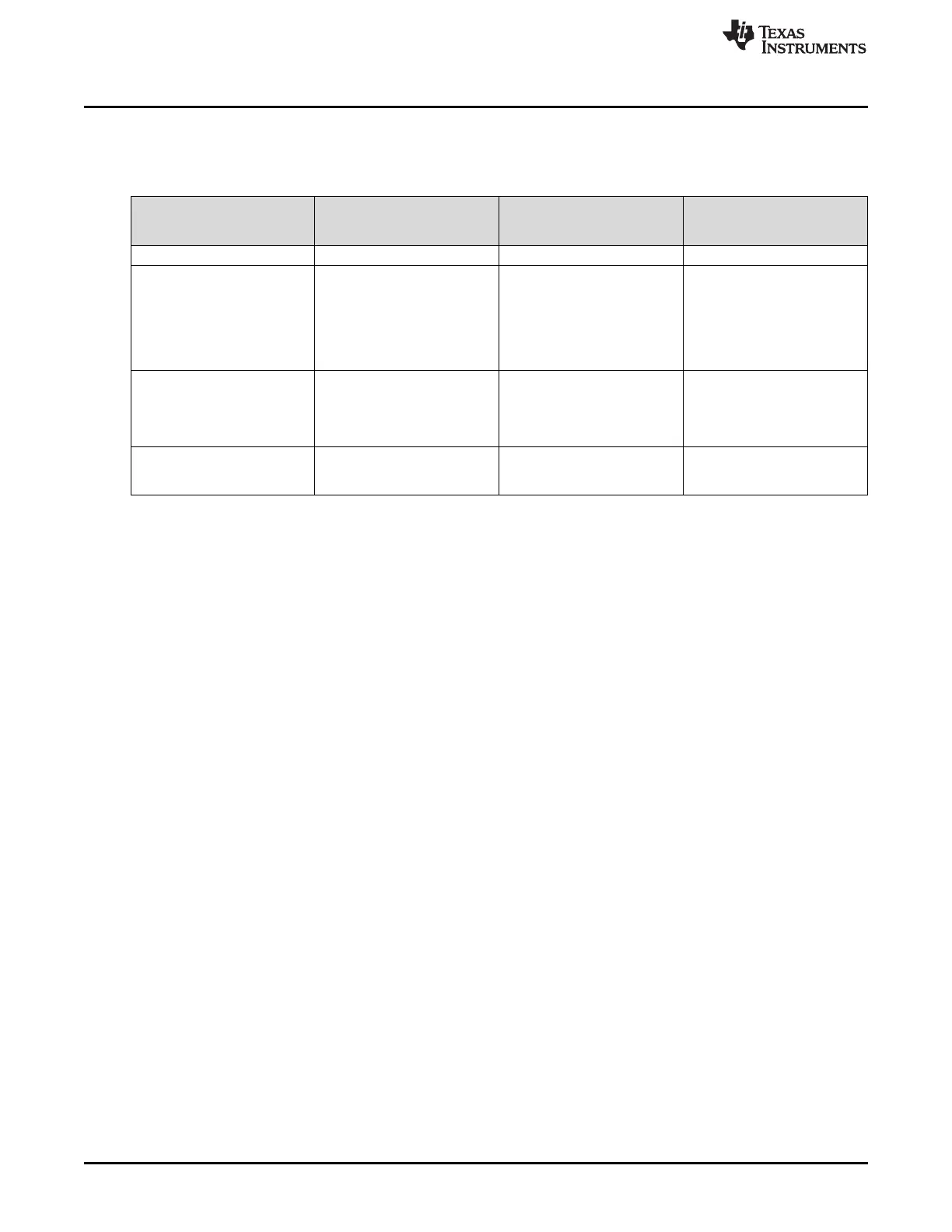
Based on the way that the controlCARD is used, additional hardware settings may be necessary, as
shown in Table 1.
Table 1. Getting Started Reference
Debug Using CCS and the
on-card xds100v2 Emulator
Debug Using CCS and an
External Emulator Through
the Baseboard
Standalone (Boot From
FLASH or Other Boot Mode)
S1:A (controlCARD) Position 1: Up (ON) Position 1: Down (OFF) Position 1: Down (OFF)
J1:A (controlCARD) Connect a mini USB cable
between J1:A and the
computer.
In CCS, use this target
configuration:
F280049C device with an
xds100v2 emulator.
— —
S1 (controlCARD) Position 1: Down (ON)
Position 2: Up (OFF)
Putting the C2000 device into
Wait Mode can reduce the risk
of connectivity issues.
Position 1: Down (ON)
Position 2: Up (OFF)
Putting the C2000 device into
Wait Mode can reduce the risk
of connectivity issues.
Set S1 as desired
Baseboard’s JTAG connector
(J2 on the Docking Station
baseboard)
—
Connect an external emulator
and appropriately configure the
CCS target configuration.
—
Code Composer Studio (CCS) is an integrated development environment (IDE) used to debug and
develop software for the C2000 series of MCUs. It can be downloaded from the following link:
http://processors.wiki.ti.com/index.php/Download_CCS.
The following PDF documents are provided to describe where each of the F28004x MCU’s pins appears
on the controlCARD connector/Docking Station:
• TMDSCNCD28004x_120cCARD_pinout_RevA – Indicates where each MCU pin is located on the
HSEC controlCARD connector or the 120/180-pin controlCARD docking station.
• TMDSCNCD28004x_DIM100Adapter_pinout_RevA – Indicates where each MCU pin is located on
the DIM100 controlCARD connector or the DIM100 docking station. This assumes that the
TMDSADAP180TO100 adapter card is used.
More information on the controlCARD/docking station can be found at the following locations:
• \ti\c2000\C2000Ware_X_XX_XX_XX\boards\controlCARDs\TMDSCNCD280049M\
• \ti\c2000\C2000Ware_X_XX_XX_XX\boards\ExperimentersKits\DockingStation_HSEC_120or180pin\
3.5 Experimentation Software
C2000Ware contains a full suite of example software designed to work with the F280049C controlCARD.
This software can be found at http://www.ti.com/tool/C2000Ware.
This example software package includes many projects which allow the user to experiment with the ADC,
PWM, and other C2000 peripherals.
4 Special Notes
4.1 xds100v2 Emulator and SCI/UART Connectivity
The F280049C controlCARD provides emulation and USB-to-UART adapter functionality on the
controlCARD. This allows for a convenient method to debug and demo the F28004x MCU.
The FTDI chip, its support circuitry, and associated isolation components are placed in Macro A, the left
section of the controlCARD. Each of these components contains an additional A within the component
reference designator (that is R2:A for resistor 2 in Macro A).
 Loading...


