Hardware References
www.ti.com
8
SPRUIC4A–January 2017–Revised December 2017
Submit Documentation Feedback
Copyright © 2017, Texas Instruments Incorporated
Piccolo F280049C controlCARD Information Guide
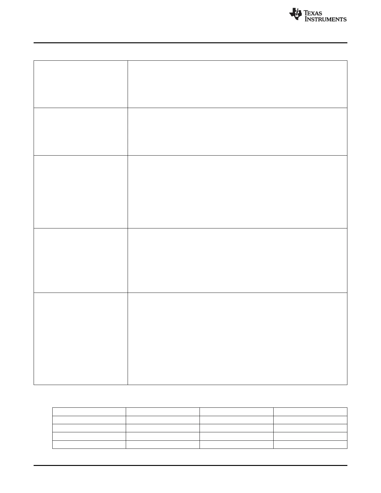
Table 2. Hardware References (continued)
S5 GPIO24/GPIO25 Configuration Switches
Switch 1 (left switch) – GPIO24 Configuration Switch:
• In the up position – GPIO24 goes to pin 75 of the HSEC connector.
• In the down position – GPIO24 goes to pin 100 of the HSEC connector.
Switch 2 (right switch) – GPIO25 Configuration Switch:
• In the up position – GPIO25 goes to pin 77 of the HSEC connector.
• In the down position – GPIO25 goes to pin 102 of the HSEC connector.
S6 GPIO26/GPIO27 Configuration Switches
Switch 1 (left switch) – GPIO26 Configuration Switch:
• In the up position – GPIO26 goes to pin 107 of the HSEC connector.
• In the down position – GPIO26 goes to pin 79 of the HSEC connector.
Switch 2 (right switch) – GPIO27 Configuration Switch:
• In the up position – GPIO27 goes to pin 109 of the HSEC connector.
• In the down position – GPIO27 goes to pin 81 of the HSEC connector.
S7 PGA Filter Configuration Switches
From the left, the switches control whether PGA1-PGA7’ s outputs, respectively, are filtered.
Switch 8 is unused.
Each switch:
• In the up position – an HSEC pin is connected to the respective PGA+ input pin, and is
now also tied to an additional ADC input pin. In software, PGA output filtering, for the
respective PGA, functionality should NOT be used.
• In the down position – an HSEC pin only goes to the PGA+ input pin. PGA output filtering,
for the respective PGA, may be used.
The description above is similar, but not quite true of S7’s switch 6 (PGA6). Its implementation is
slightly different; see the schematic for details. The switch does still give whether PGA output
filtering may or may not be used.
S8 ADC VREFHI Control Switch for ADC modules
Switch 1 (left switch) – VREFHI Control Switch for ADC module A:
• In the up position – ADC-A is configured to use an external voltage reference, which should
be connected to pin 45 of the HSEC connector.
• In the down position – ADC-A should be configured to use the internal voltage reference.
Switch 2 (right switch) – VREFHI Control Switch for ADC module B and module C:
• In the up position – ADC-B and ADC-C are configured to use an external voltage reference,
which should be connected to pin 45 of the HSEC connector.
• In the down position – ADC-B and ADC-C should be configured to use the internal voltage
reference.
S1:A Isolated emulation and UART communication enable switches
Switch Position 1 – JTAG Enable:
• ON – All signals between the xds100v2 emulation logic and the MCU are connected. This
setting is valid when the MCU is being debugged or programmed through the on-card
xds100v2 emulator.
• OFF – The xds100v2 emulation logic will NOT be connected to the MCU. This setting is
valid when the device boots from FLASH, boots from a peripheral directly, or when an
external JTAG emulator is used.
Switch Position 2 – ISO UART communication enable:
• ON – The C2000 MCU’s GPIO-28 (and pin76 of the 180pin controlCARD connector) are
coupled to the FTDI’s USB-to-Serial adapter. This allows UART communication to a
computer through the FTDI chip. However, in this position, GPIO-28 is forced high by the
FTDI chip. Functionality of pin76 on the connector is limited.
• OFF – The C2000 MCU will NOT be connected to the FTDI USB-to-Serial adapter. Pin76 of
the 180pin controlCARD connector is directly connected to GPIO-28.
Table 3. Boot Mode Switch Positions
Mode # Switch Position 1 (GPIO-24) Switch Position 2 (GPIO-32) Boot from
00 0 0 Parallel I/O
01 0 1 Boot from SCI / Wait Mode
02 1 0 Boot from CAN
03 1 1 Boot from FLASH
 Loading...


