www.ti.com
Special Notes
5
SPRUIC4A–January 2017–Revised December 2017
Submit Documentation Feedback
Copyright © 2017, Texas Instruments Incorporated
Piccolo F280049C controlCARD Information Guide
Each F280049C controlCARD’s xds100v2 is programmed with a fixed serial number. If a debug session
must involve two or more F280049C controlCARDs, each controlCARDs must have a unique serial
number, and some must be reprogrammed. See:
http://processors.wiki.ti.com/index.php/XDS100#Q:_Can_I_change_the_serial_number_on_my_XDS100v2
.3F.
The configuration of the switches on S1:A determine whether the on-board emulator is active, whether an
external emulator can be used, or whether the device will boot from FLASH/peripherals. See Figure 2 .
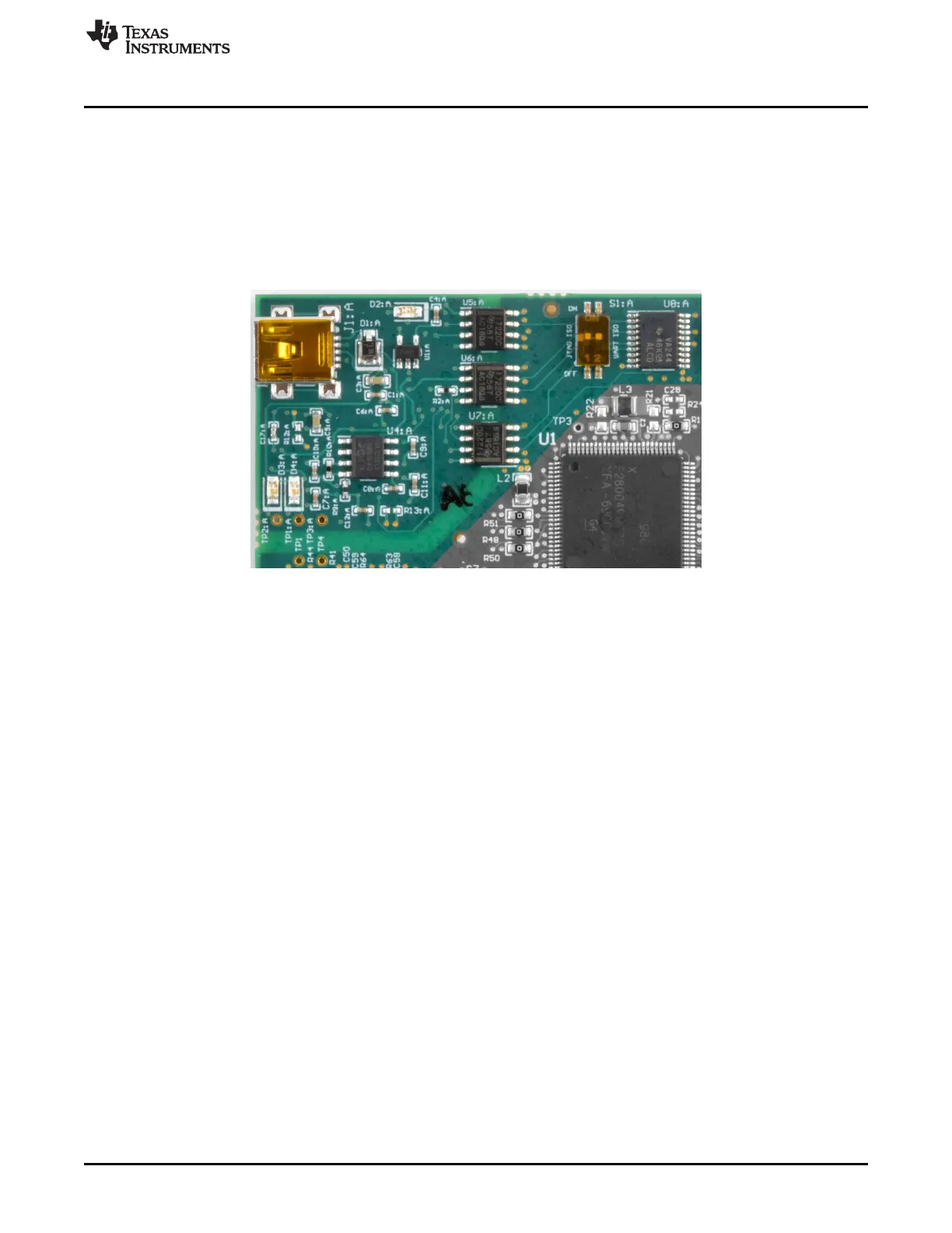
Figure 2. xds100v2 Emulation Circuitry and Isolation Circuitry is Denoted by :A
4.2 cJTAG Usage
The F280049C MCU supports the cJTAG 2-pin debugging interface. The controlCARD's onboard
xds100v2 emulator does not support cJTAG; however, the controlCARD enables a customer to
experiment with cJTAG using an external emulator connected to the baseboard. To enable cJTAG:
1. Connect an external emulator to the controlCARD's baseboard.
2. Change S4 to the cJTAG position (switch flipped up).
3. If cJTAG is used, the F280049C MCU will have two additional GPIO which can be used by the
application. Configure S2 and S3, as desired, to control which controlCARD fingers or pins the newly
available GPIO is connected to.
4.3 Supporting Evaluation of the Internal DC/DC Converter
The controlCARD, by default, assumes the F280049 internal VREG will be used to generate the 1.2-V
power supply required by the MCU. The controlCARD enables the user to utilize the internal DC/DC
converter capabilities, with some soldering.
To enable the internal DC/DC converter:
• R18 and R19 must be unpopulated.
• R21 and R22 must be populated with a 0-Ω resistor.
• C19 must be populated with a 2.2-µF X5R/X7R capacitor.
• C20 and C21 must each be populated with a 10-µF X5R/X7R capacitor.
Functionally, the F280049C powers up the 1.2-V power rail using the internal VREG, then requires
software to change from the VREG to the DC/DC. See the F28004x Technical Reference Manual for more
details.

 Loading...

