TMS320E25
SPRS010B — MAY 1987 — REVISED NOVEMBER 1990
POST OFFICE BOX 1443 HOUSTON, TEXAS 77001
62
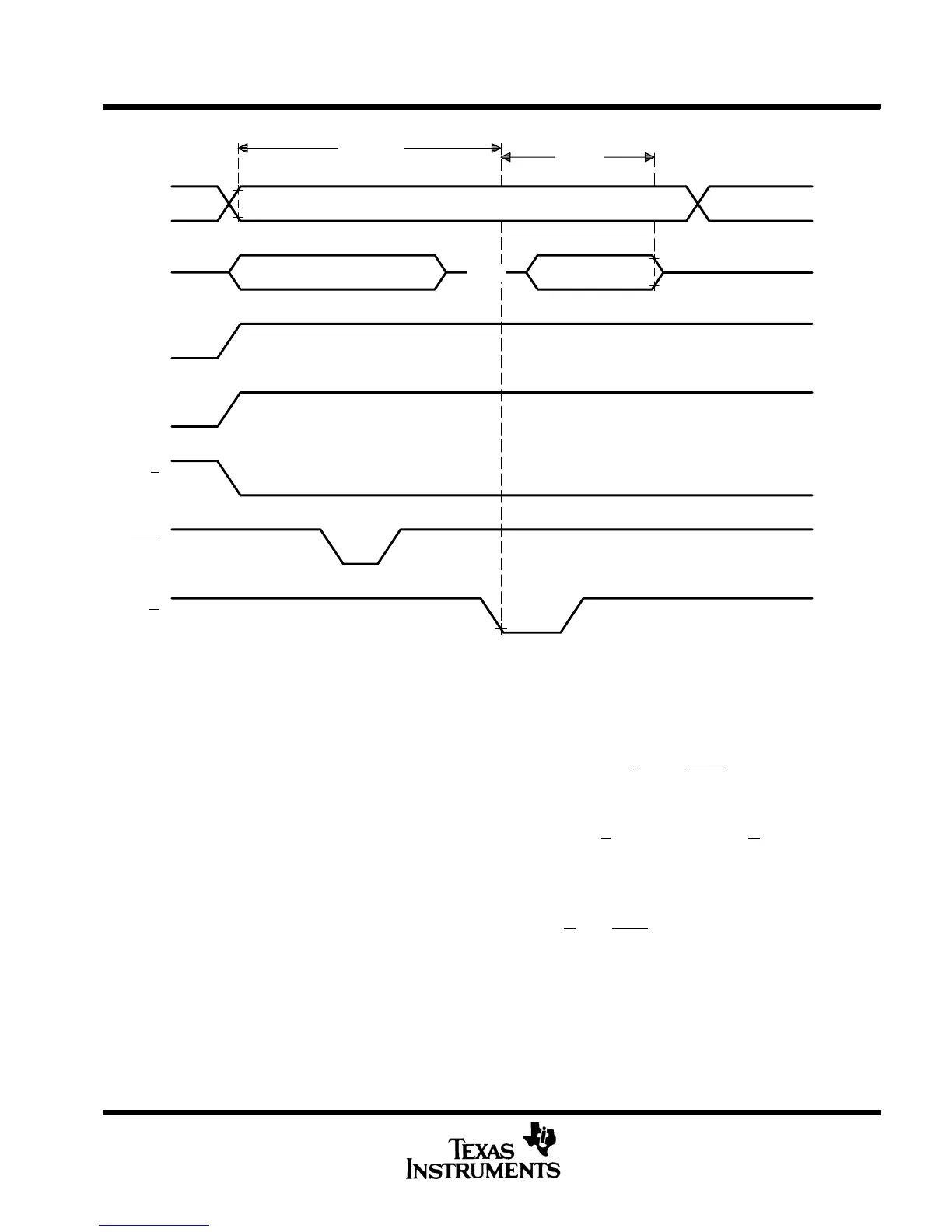
Address Stable Address N + 1
Data In Stable Data Out Valid
HI-Z
Program
Verify
V
IH
V
IL
V
IH
/V
OH
V
IL
/V
OL
V
PP
V
CC
V
CC + 1
V
CC
V
IH
V
IL
V
IH
V
IL
V
IH
V
IL
A12-A0
Q8-Q1
V
PP
V
CC
E
PGM
G
Figure 11. Fast Programming Timing
program inhibit
Programming may be inhibited by maintaining a high level input on the E
pin or PGM pin.
read
The EPROM contents may be read independent of the programming cycle, provided the RBIT (ROM protect
bit) has not been programmed. The read is accomplished by setting E
to zero and pulsing G low. The contents
of the EPROM location selected by the value on the address inputs appear on Q8-Q1.
output disable
During the EPROM programming process, the EPROM data outputs may be disabled, if desired, by establishing
the output disable state. This state is selected by setting the G
and PGM pins high. While output disable is
selected, Q8-Q1 are placed in the high-impedance state.
ROM protection and verification
This section describes the code protection feature included in the EPROM cell, which protects code against
copyright violations. Table 6 shows the programming levels required for protecting and verifying the EPROM.
The paragraphs following the table describe the protect and verify functions.
ADVANCE INFORMATION

 Loading...


