www.ti.com
TPA3255EVM Setup
7
SLOU441–July 2016
Submit Documentation Feedback
Copyright © 2016, Texas Instruments Incorporated
TPA3255EVM
3.3 Hardware Default Setup BTL (2.0)
BTL (2.0) default hardware setup is as follows:
• Remove the EVM from the ESD bag.
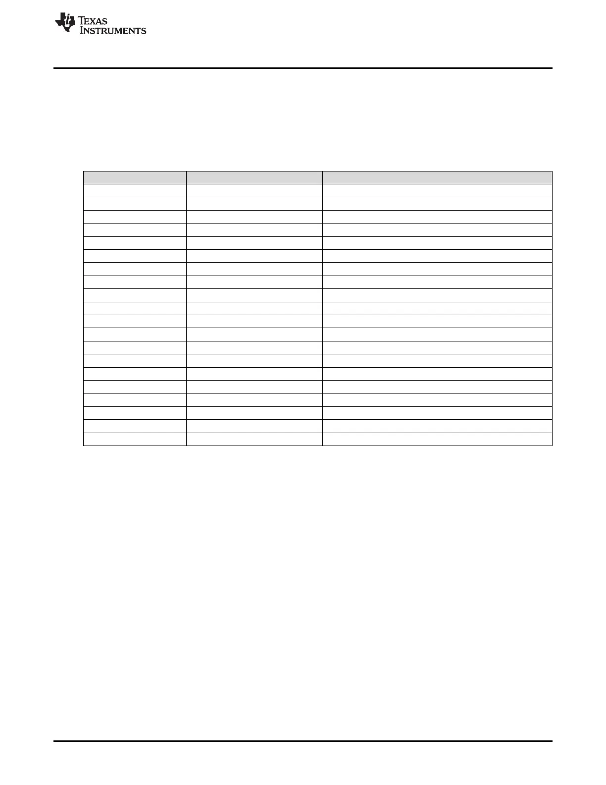
• Check that jumpers are in their default state as shown in Figure 1 and Table 3 for stereo BTL
operation:
Table 3. Stereo BTL Default Jumper States
Jumper Setting Comment
J29 IN PVDD to 15-V BUCK
J31 IN 12-V LDO to 12-V TERM
J32 IN 3.3-V LDO to 3.3-V TERM
J33 IN 3.3-V LDO to 3.3-V TERM
J21 IN CSTART SE
J16 3 to 4 MASTER MODE
J5 2 to 3 M1 – BTL
J6 2 to 3 M2 – BTL
J22 IN OUTA CAP SHUNT
J23 IN OUTB CAP SHUNT
J24 IN OUTC CAP SHUNT
J25 IN OUTD CAP SHUNT
J26 2 to 3 INC SELECT
J27 2 to 3 IND SELECT
J7 OUT PBTL SELECT INC
J8 OUT PBTL SELECT IND
J10 OUT INC/D DIFF INPUT
J12 OUT INC/D DIFF INPUT
J4 1 to 2 INA/B SE INPUT
J19 1 to 2 INC/D SE INPUT
• Set S1 to the RESET position.
• Set power supply to 51 V (14–53.5-V range) and current to 10 A (5–14-A range). Do not power up until
all connections are completed.
• Connect power supply to TPA3255 EVM positive terminal to PVDD (RED) and negative terminal to
GND (BLACK).
• Connect left channel speaker/power resistor load (4–8 Ω) to TPA3255 EVM positive output terminal to
OUTA (RED) and AP analog input channel A positive terminal.
• Connect left channel speaker/power resistor load (4–8 Ω) to TPA3255 EVM negative output terminal to
OUTB (BLACK) and AP analog input channel A negative terminal.
• Connect right channel speaker/power resistor load (4–8 Ω) to TPA3255 EVM positive output terminal
to OUTC (RED) and AP analog input channel B positive terminal.
• Connect right channel speaker/power resistor load (4–8 Ω) to TPA3255 EVM negative output terminal
to OUTD (BLACK) and AP analog input channel B negative terminal.
• Be careful not to mix up PVDD, OUTA, and OUTB terminals, since the colors are the same ( RED).
• For single-ended stereo inputs, connect AP channel A XLR to RCA male jacks to female RCA jacks
input A/AB (RED) and AP channel B XLR to RCA male jacks to female RCA jacks input C/CD (WHITE)
and set J4 and J19 jumper positions to SE.
• For differential stereo inputs, connect positive RCA male jacks to female RCA jacks input A/AB
(RED) and input C/CD (WHITE) and connect negative RCA male jacks to female RCA jacks input B
(BLUE) and input D (BLACK) and set J4 and J19 jumper positions to DIFF.
• Power up power supply once all the connections are made correctly and the 3.3-V and12-V LEDs
(GREEN) will illuminate.