www.ti.com
Using TPA3255EVM in Different Output Configurations
9
SLOU441–July 2016
Submit Documentation Feedback
Copyright © 2016, Texas Instruments Incorporated
TPA3255EVM
4 Using TPA3255EVM in Different Output Configurations
The TPA3255EVM can be configured for four different output operations. The 2.0 BTL configuration is the
default set up of the TPA3255EVM described in Section 3.3. The remaining three configurations are 2.1
BTL plus two single-ended (SE) outputs, 0.1 PBTL output, and 4.0 single-ended (SE) outputs.
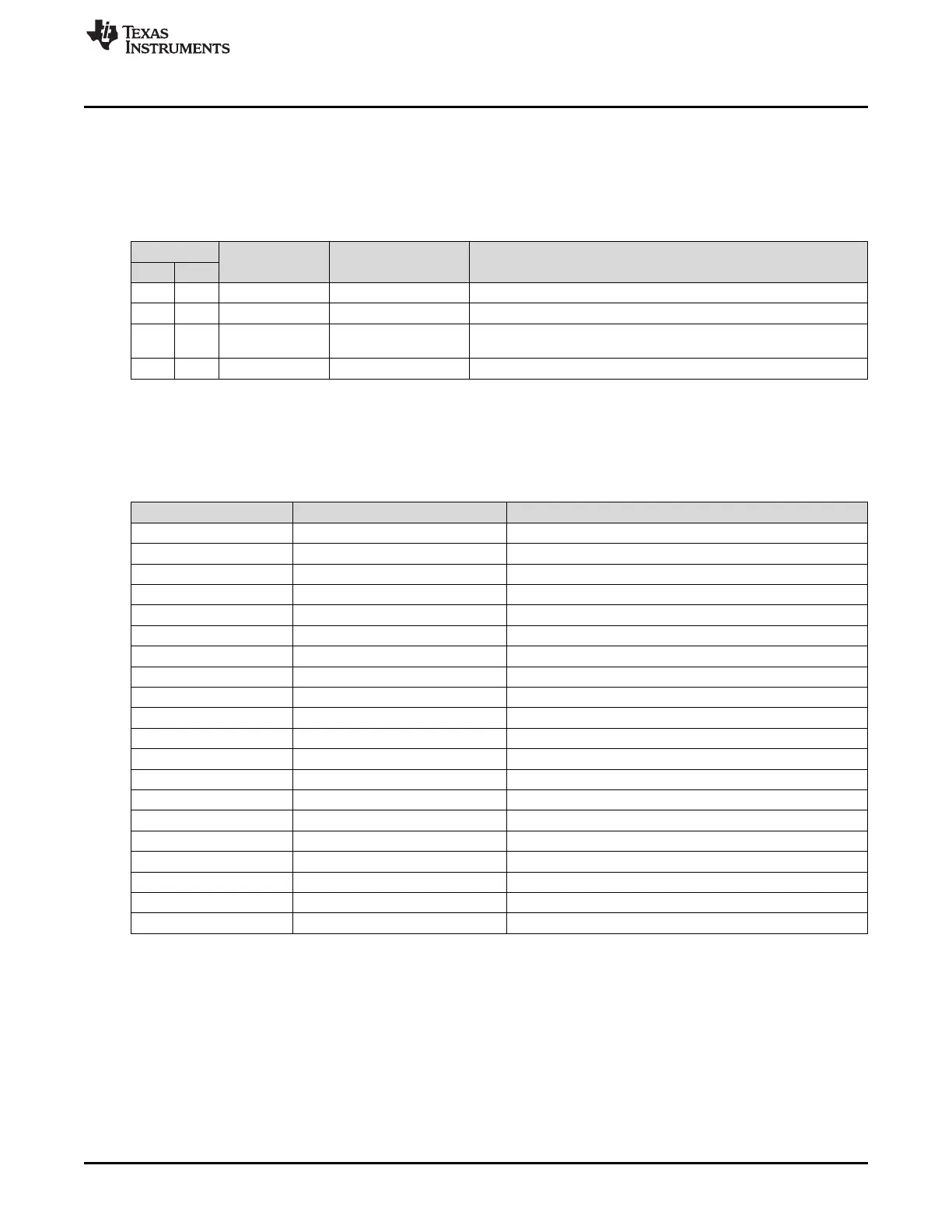
Table 4. Mode Selection Pins
Mode Pins
Input Mode Output Configuration Description
M2 M1
0 0 2N + 1 2 × BTL Stereo BTL output configuration
0 1 2N/1N + 1 1 × BTL + 2 × SE 2.1 BTL + SE mode
1 0 2N + 1 1 × PBTL
Paralleled BTL configuration. Connect INPUT_C and INPUT_D to
GND.
1 1 1N + 1 4 × SE Single-ended output configuration
4.1 BTL Plus Two SE (2.1) Operation
Configure the EVM as follows for 2 SE + 1 BTL operation:
Table 5. 2 SE + 1 BTL Default Jumper States
Jumper Setting Comment
J29 IN PVDD to 15-V BUCK
J31 IN 12-V LDO to 12-V TERM
J32 IN 3.3-V LDO to 3.3-V TERM
J33 IN 3.3-V LDO to 3.3-V TERM
J21 IN CSTART SE
J16 3 to 4 MASTER MODE
J5 1 to 2 M1 – 2XSE + BTL
J6 2 to 3 M2 - 2XSE + BTL
J22 IN OUTA CAP SHUNT
J23 IN OUTB CAP SHUNT
J24 OUT OUTC CAP SHUNT
J25 OUT OUTD CAP SHUNT
J26 2 to 3 INC SELECT
J27 2 to 3 IND SELECT
J7 OUT PBTL SELECT INC
J8 OUT PBTL SELECT IND
J10 OUT INC/D DIFF INPUT
J12 OUT INC/D DIFF INPUT
J4 1 to 2 INA/B SE INPUT
J19 1 to 2 INC/D SE INPUT
• Set J6 to L and J5 to H.
• Connect left (stereo) speaker/power resistor load (2–4 Ω) positive terminal to OUTC and remove
jumper J24.
• Connect right (stereo) speaker/power resistor load (2–4 Ω) positive terminal to OUTD and remove
jumper J25.
• Connect subwoofer (mono) speaker/power resistor load (4–8 Ω) positive terminal to OUTA and
negative terminal to OUTB.
• Set J19 jumper position to DIFF.
• Connect left (stereo) channel input to female RCA jack input C/CD ( WHITE) for OUTC speaker.