Premier Elite Speech Module
INSTALLATION INSTRUCTIONS
Introduction
The Premier Elite Speech Module provides four recordable 10 second audio messages, each
message is assigned to a Digi Channel, which in turn can be triggered from one of the many output
functions of the control panel. A COM2400 must be installed to enable the Premier Elite Speech
Module, it will not function with a COM300. Only the first four Digi Channels are used by the
Premier Elite Speech Module. The Premier Elite Speech Module is supported by the following
Texecom control panels:
• Premier Elite all models factory built V3 and later, all models fitted with a DTMF decoder.
If the Speech Module is fitted to a V3 panel that does not have the DTMF decoder chip fitted,
it may not be possible to acknowledge the received calls. This will result in repeated calls
until all programmed dial attempts have been used..
Hardware Identification
Premier Elite 24
The DTMF chip is located below the Barcode
label and is identified with a green dot.
Premier Elite 48/88/168 & 640
The DTMF chip is located just below the
digi pins and is identified with a green dot.
Premier Elite 12-W/24-W/48-W
The DTMF chip is located to the left of the
main processor and is identified with a
green dot.
PCB Layout and Connections
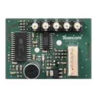
The figure below shows the PCB layout of the Premier Elite Speech Module.
Microphone
Record/Play Indicator
Control panel connector
Record Buttons
Figure 1. Premier Elite Speech Module PCB Layout
Figure 2. Premier Elite Speech Module Connected to Expansion Port on PCB
Premier Elite Speech Module Installation
To install the Premier Elite Speech Module proceed as follows:
Ensure that all power is removed from the control panel before connecting the Premier Elite
Speech Module.
Plug the Premier Elite Speech Module (see Figure 2) onto the 7 way Expansion Port of the control
panel.
Plug the COM2400 onto the onboard digi pins, and connect to a telephone line. When using an
RJ11 plug, this should be connected before the COM2400 is fitted in place.
Re-apply power to the system and proceed to the next section.
Premier Elite Speech Module Locations
Use the self-adhesive mounting posts to locate the Speech Module as shown.
Premier Elite Small Polymer Housing (e.g. 12-W Live) mount to the rear of the housing
Premier Elite Large Polymer Housing (e.g. 24 & 48-W) mount to the inner wall of the housing
Premier Elite Metal Housing (e.g. 48.88 & 168) mount inside the top of the housing.
Tamp
Strb 0V Bell+12V Op1
Aux
12V
Spk -
Bell
Aux 12VNetwork
F4
F3
F1
F6
Engineer
Remote
Com2
Com1
Load Defaults
Tx
Rx
+
-
Aux/Fault
Bell +12V
Enable
Network
2 Wire
Smoke
Enable
Expansion
Batt Charge
0.75A 0.3A
Kick Start
F2
Batt
DC
F8
F9
!
USE WITH
TEXECOM PSU
ONLY
Com 2
F1
F5
JP7
Aux 12v
1Amp
Network 2
1Amp
Com 1
Heartbeat
Load
Defaults
Expansion
F3
Network 1
1Amp
Kick
Start
Tx1
Rx1
Tx2 Rx2
Box
Tamp
100mV = 1Amp
V
F6
F2
F8
F7
F9
!
USE WITH
TEXECOM PSU
ONLY
F4
Eng Keypad
Bell/Strb - 1Amp
JP10
Engineer REM
OPTIONS
Tamper
Disable
100 Vm = 1 Amp
V
F3
F4
F5
F6
F1
F8
Batt Charge
0.75A 0.3A
F2
!
BAR CODE
USE WITH
TEXECOM PSU
ONLY
F7
Com 2
F1
F5
JP7
Aux 12v
1Amp
Network 2
1Amp
Com 1
Load
Defaults
Expansion
F3
Network 1
1Amp
Tx1
Rx1
Tx2
Rx2
F9
Eng Keypad