Greenlee / A Textron Company 3 4455 Boeing Dr. • Rockford, IL 61109-2988 USA • 815-397-7070
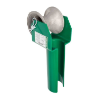
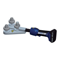
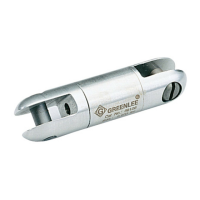
Swivels
Dimensions and weights subject to change without notice.
The Underground Safe Working Limit is calculated using a 3:1 safety factor based on the ultimate load.
The Overhead Safe Working Limit is calculated using a 5:1 safety factor based on the ultimate load.
The Ultimate Load is the tensile load required to separate the swivel into two or more parts.
Operating Specifications
A
H
G
F
D
E
C
B
E
NOTE:
Slotted clevis pins are supplied standard
on swivels 39106 and 39107.
Hex clevis pins are supplied standard on
swivels 39108 - 39111.
Underground Overhead
Part No. Safe Working Safe Working A B C D E F G H
Net
Limit Limit
Weight
39106 2,250 lb 1,350 lb 7/8" 3/8" 5/16" 31/32" 7/16" 2-1/2" 3-3/8" 7/32" 0.33 lb
10 kN 6.0 kN 22 mm 9.5 mm 7.9 mm 24.6 mm 11.1 mm 64 mm 86 mm 0.15 kg
39107 5,000 lb 3,000 lb 1-1/4" 17/32" 13/32" 1-9/32" 17/32" 3-11/16" 4-3/4" 1/4" 1.0 lb
22 kN 13 kN 32 mm 13.5 mm 10.3 mm 32.5 mm 13.5 mm 94 mm 121 mm 0.45 kg
39108 7,000 lb 4,200 lb 1-3/8" 9/16" 1/2" 1-3/8" 5/8" 3-7/8" 5-1/8" 5/16" 1.4 lb
31 kN 19 kN 35 mm 14.3 mm 12.7 mm 35.0 mm 15.9 mm 98 mm 130 mm 0.63 kg
39109 10,000 lb 6,000 lb 1-5/8" 11/16" 5/8" 1-23/32" 3/4" 4-1/2" 6" 3/8" 2.1 lb
45 kN 27 kN 41 mm 17.5 mm 15.9 mm 43.7 mm 19.1 mm 114 mm 152 mm 0.95 kg
39110 15,000 lb 9,000 lb 2" 25/32" 11/16" 2-1/16" 15/16" 5-1/8" 7" 3/8" 3.8 lb
67 kN 40 kN 51 mm 19.8 mm 17.5 mm 52.4 mm 23.8 mm 130 mm 178 mm 1.7 kg
39111 25,000 lb 15,000 lb 2-3/8" 1-1/32" 7/8" 2-25/32" 1-3/16" 7-5/8" 10" 3/8" 7.6 lb
112 kN 67 kN 60 mm 26.2 mm 22.2 mm 70.6 mm 30.2 mm 194 mm 254 mm 3.5 kg
KEEP THIS MANUAL
All specifications are nominal and may change as design improve-
ments occur. Greenlee Textron shall not be liable for damages
resulting from misapplication or misuse of its products.
 Loading...