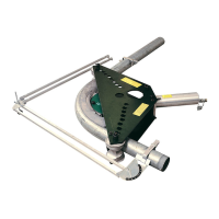
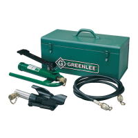
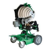
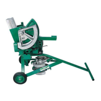
884 and 885 Hydraulic Benders
Greenlee / A Textron Company 4455 Boeing Dr. • Rockford, IL 61109-2988 USA • 815-397-7070
12
Bending Instructions (cont’d)
Laying Out a Segment Bend (cont’d)
Ram Travel Constants Table
Conduit or Pipe Size 1/2" 3/4" 1" 1-1/4" 1-1/2" 2" 2-1/2" 3" 3-1/2" 4"
“D” 5.2 5.2 5.2 5.2 5.2 6.2 7.1 8.1 9.1 10.2
To use this table, nd the conduit or pipe size in the top
row, and nd the constant “D” that corresponds to that
size. Divide constant “D” by the number of bends to be
made. The result is the amount of ram travel per bend
required after the shoe contacts the conduit or pipe.
Gain Factor Table
Angle—
Increments by Tens
Angle—Increments by Ones
— 1° 2° 3° 4° 5° 6° 7° 8° 9°
0° 0.0000 0.0000 0.0000 0.0000 0.0000 0.0000 0.0001 0.0001 0.0003 0.0003
10° 0.0005 0.0006 0.0008 0.0010 0.0013 0.0015 0.0018 0.0022 0.0026 0.0031
20° 0.0036 0.0042 0.0048 0.0055 0.0062 0.0071 0.0079 0.0090 0.0100 0.0111
30° 0.0126 0.0136 0.0150 0.0165 0.0181 0.0197 0.0215 0.0234 0.0254 0.0276
40° 0.0298 0.0322 0.0347 0.0373 0.0400 0.0430 0.0461 0.0493 0.0527 0.0562
50° 0.0600 0.0637 0.0679 0.0721 0.0766 0.0812 0.0860 0.0911 0.0963 0.1018
60° 0.1075 0.1134 0.1196 0.1260 0.1327 0.1398 0.1469 0.1544 0.1622 0.1703
70° 0.1787 0.1874 0.1964 0.2058 0.2156 0.2257 0.2361 0.2470 0.2582 0.2699
80° 0.2819 0.2944 0.3074 0.3208 0.3347 0.3491 0.3640 0.3795 0.3955 0.4121
90° 0.4292 — — — — — — — — —
To use this table, nd the gain factor by nding the inter-
section of the appropriate row (“tens” digit of the angle)
and appropriate column (“ones” digit of the angle). Refer
to the following example.
Example: 64° bend
15" centerline radius
Correct row: 60°
Correct column: 4°
Gain factor: 0.1327
Gain for total bend: 0.1327 x 15 = 1.9905
Round up to nearest whole
number or common fraction.
Gain for total bend: 2"
 Loading...