©Copyright Task Force Tips LLC 2000-2020 LIM-025 June 23, 2010 Rev08
5
3.3 ELECTRIC INSTALLATION
Non-plug version of nozzles with electric stream shaper actuation are shipped with wiring diagram LIM-040. For plug version nozzle
installation, refer to LIY-500 Remote Control (RC) Monitor Electrical Controls (shipped with TFT Monitors or available at tft.com).
Max-series ER nozzles are equipped with manual override in case of electrical power failure.
This device is not rated as ignition proof, explosion proof, or intrinsically safe. Use only in
locations with adequate ventilation and no hazard of ammable vapor buildup.
3.4 PATTERN CONTROL
Max-Series nozzles have full pattern control from straight stream to wide fog. The pattern can be adjusted using the linear actuator
either by electronic control or by twisting the OVERRIDE KNOB in either direction. Moving the STREAM SHAPER forward transitions
the SHAPER to the straight stream position. Moving the SHAPER rearward will result in an increasingly wider pattern.
For manually operated nozzles, turning the stream shaper clockwise (as seen from the operating position behind the nozzle) moves
the shaper to the straight stream position. Turning the shaper counterclockwise will result in an increasingly wider pattern.
Since the stream trim point varies with ow, the stream should be “trimmed” after changing the ow to obtain the straightest and
farthest reaching stream. To properly trim the stream, rst open the pattern to narrow fog. Then close the stream to parallel to give
maximum reach. Note: Turning the shaper further forward will cause stream crossover and reduce the eective reach of the nozzle.
The nozzle reaction is greatest when the shaper is in the straight stream position. The nozzle operator must be prepared for a change
in reaction as the pattern is changed.
Care must be taken to avoid dents or nicks in the nozzle tip. Dents or nicks can seriously aect the stream reach.
3.5 FLUSH CONTROL
Small debris passes through the debris screen (if so equipped) and may get caught inside the nozzle. This trapped material will
cause poor stream quality, shortened reach, and reduced ow.
To remove trapped debris, the ER nozzle can be ushed as follows: while still owing water, move the SHAPER rearward past the
full fog position until it stops traveling. This will open the nozzle allowing debris to pass through. Move the SHAPER forward and out
of the ush position to continue normal operation.
When used with a TFT RC Monitor equipped with Smart Stream technology, the Fog button must be pressed and held a second time
to reach the Flush position, shown in Figure 3. The purpose of the Smart Stream feature is to prevent unintentional ushing of the
nozzle, which will reduce reach and increase the ow rate, potentially depleting the water supply more quickly.
To remove small debris, the manually operated nozzle may be ushed as follows:
While still owing water, rotate the SHAPER counterclockwise (as viewed from behind the nozzle) to the ush position. (increased
resistance will be felt on the SHAPER as the nozzle goes into ush) This will open the nozzle allowing debris to pass through.
During ush the nozzle reaction will decrease as the pattern becomes wider and the pressure drops. The nozzle operator must be
prepared for an increase of nozzle reaction when returning the nozzle from the ush position to retain control of the nozzle.
Rotate the SHAPER out of ush to continue normal operations.
Large amounts or pieces of debris may be unushable and can reduce the ow of the nozzle
resulting in an ineective ow. In the event of a blockage, it may be necessary to retreat to a safe
area, uncouple the nozzle and remove debris.
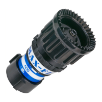
3.6 STANDARD/LOW PRESSURE KNOB (MAX-FORCE)
For situations where 100 psi at the nozzle is impractical, the Max-Force dual pressure knob may be switched to low pressure mode.
In the low pressure mode, the nozzle pressure is reduced by about 50%, while maintaining a usable stream and increasing the ow.
The nozzle operator must be prepared for a change in reaction when changing modes.
To switch to the low pressure mode, shut o water ow to nozzle and turn knob at front of nozzle counterclockwise (when viewed from
front). Nozzle will now operate at reduced pressure. Repeat the process, except turn knob clockwise, to return to 100 psi operation.
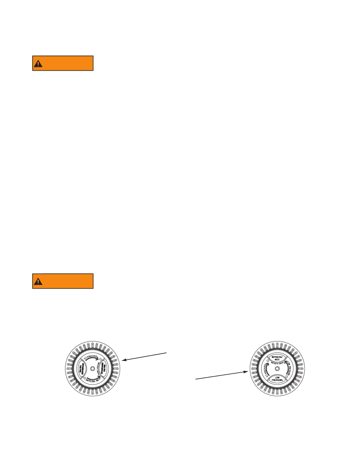
Knob In
Standard
Operating Mode
Knob In
Low Pressure
Figure 3.6
 Loading...