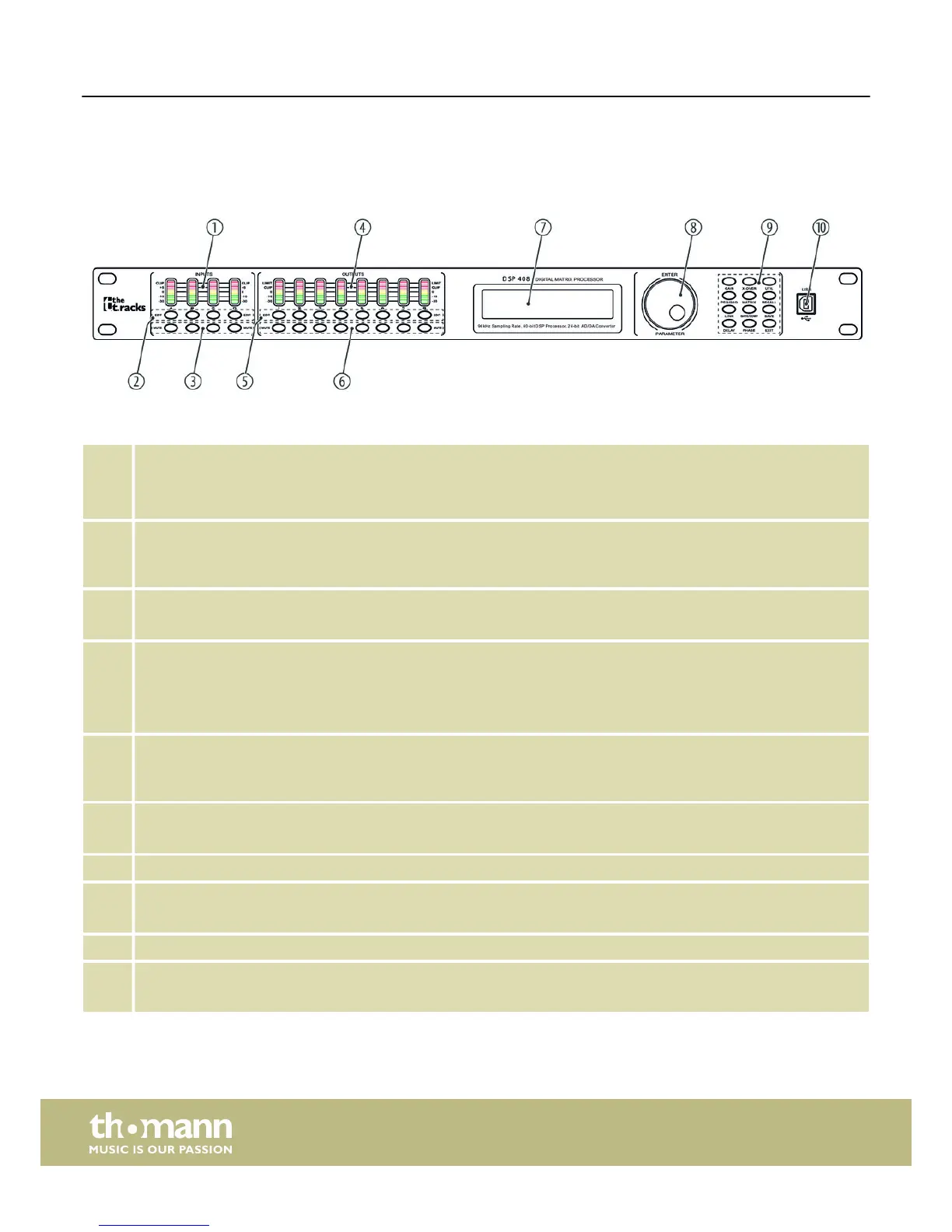
5 Connections and controls
1 [INPUTS]
Level indicator for the input channels. The number of channels depends on the device design.
The red [CLIP] LEDs indicate overload (clipping). In this case the level of the input signal is too high.
2 [EDIT]
Buttons for selecting the edit mode for the respective input channel. The set parameters of the selected channel
appear in the display.
3 [MUTE]
Buttons for muting or unmuting the respective input channel.
4 [OUTPUTS]
Level indicator for the output channels. The number of channels depends on the device design.
The red [CLIP] LEDs indicate overload (clipping). In this case the level of the output signal is too high. The red [LIMIT]
LEDs indicate that the built-in limiter has been tripped.
5 [EDIT]
Buttons for selecting the edit mode for the respective output channel. The set parameters of the selected channel
appear in the display.
6 [MUTE]
Buttons for muting or unmuting the respective output channel.
7 Display
8 [ENTER / PARAMETER]
Jog wheel
9 Buttons for direct selection of a parameter. Use the [EXIT] button to leave the edit mode.
10 [USB]
USB port
Front panel
Connections and controls
Digital speaker management system
10
 Loading...