Range Meaning
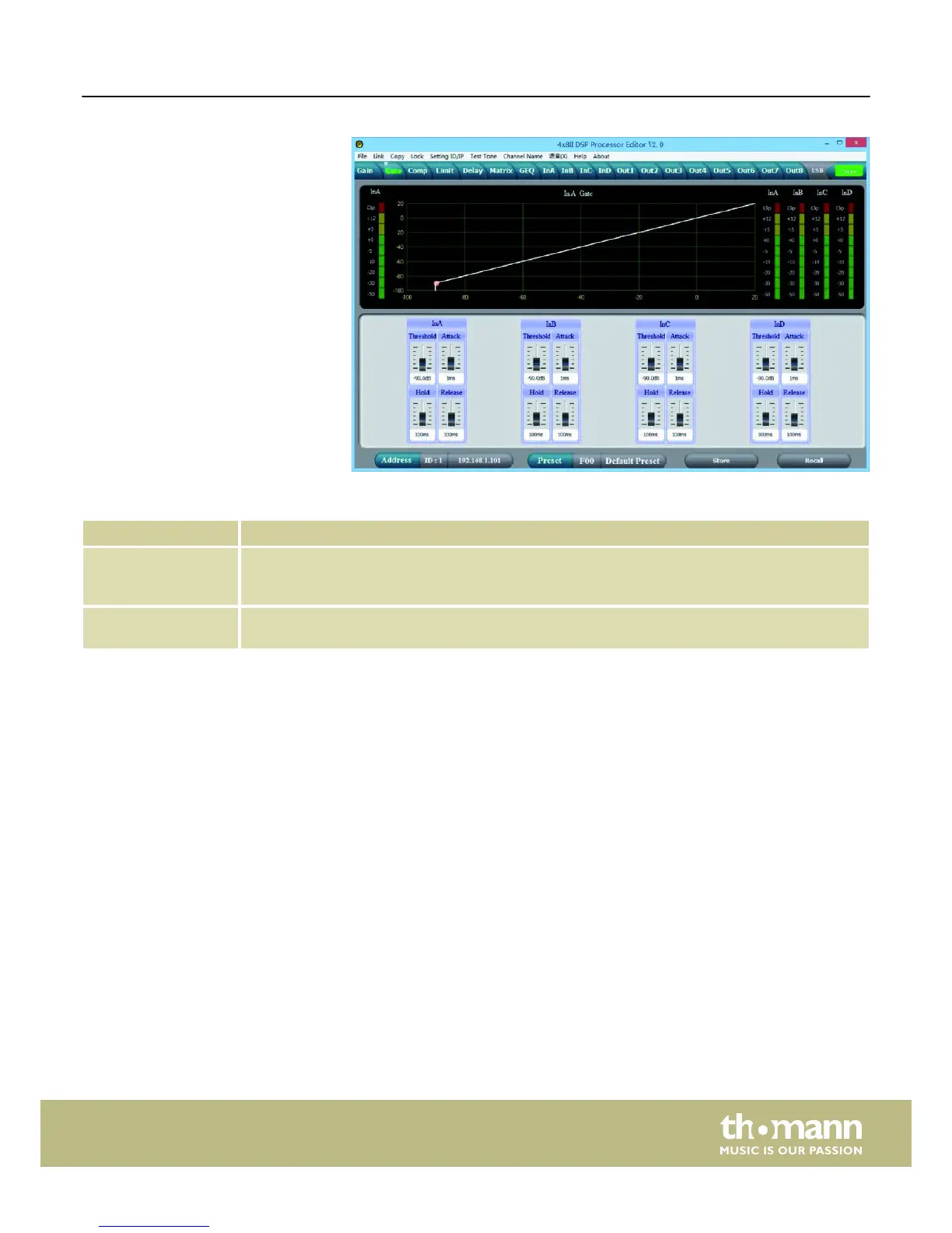
Display area Shows the current settings of the noise gate for the respective channel, with a symbolic level indi-
cator symbol appearing next to it for the input channels. The red dot on the curve represents the cur-
rent signal.
Control area Drag the fader with the mouse to set the noise gate parameters for all input and output channels:
Threshold, hold, attack, release
“Gate” tab
Control on the computer
DSP 204, DSP 206, DSP 306, DSP 408
21
 Loading...