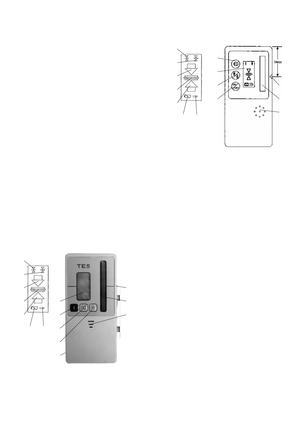
5. Receiver
Turn on the receiver by pushing the On/Off button (12) and select requested
function: Fine (14) or coarse (15) setting with button (11) (basic setting for TE 4/5
is coarse) and acoustic signal with button (7). Selected function is shown on the
LCD display (10). In addition to this, the arrow symbols (16) on the display inform,
in which direction the receiver has to be moved, while measuring.
Turn the sensor window (8) into the direction of the Quickset and move up and
down through the rotating laser beam, until the LCD display shows the arrow
symbols. Move the receiver in the direction of the arrow and stop, when the center
bar (17) is shown constantly.
If the buzzer (7) is activated, there will be a permanent sound, when the center
bar is shown. When the arrows (16) are displayed, there will be a pulsating sound,
which will be different, dependent on the position of the receiver over or under the
center hight.
TE 5 has two different settings for the sound intensity of the buzzer.
If the laser beam does not hit the beam receiving window (8) for more then 7
minutes, the receiver will turn off.
Operating elements for TE 4, TE 5:
(
7
)
Button / Figure:
Buzzer
(
8
)
B
eam receiving window
(
9
)
Center notch
(1
0
)
LCD
-
Display (front and rear)
(11) Button Fine/Coarse
(1
2
)
Button On/Off
(1
3
)
Holes for Buzzer
(
14
)
Figure Fine
(
15
)
Figure Rough
(
16
)
Arrows for
moving direction
(
17
)
C
enter bar
(
18
)
B
attery indicator
(
19
) Figu
re On
(2
0
) Battery case
TE
4
15
16
TE
5
6
. Calibration check
Set up levelling instrument as described in section 2. onto an extremely well
levelled tripod, and along a measurin
g range of approx. 30 metres
–
for example
in the X
-
axis direction
–
level and turn on.
Place a mark at the end of the measuring range at the height of the laser beam.
Subsequently, turn the laser 180° and place a second mark. Afterwards, carry out
the sam
e test along the Y
-
axis If all marks are at equal height or hardly deviate
(max.
3
mm), the calibration is correct. If larger deviations are found, the unit must
be re
-
calibrated by an authorised workshop.
7
. Supplier’s / Safety information
The unit is d
esigned in accordance with European Standards 89/336/EEC
Electromagnetic Compatibility and 73/23/EEC Electric Equipment for use within
certain voltage limits (Low
-
voltage Directive).
For evaluation purposes, the harmonised Standards EN
61326,
EN
55022,
EN
61000
-4-
2, EN 610
00-4-3
and EN 60825
-
1 have been applied.
Safety information label is placed on the
case
of the instrument.
A Class 3
R
embedded laser has been installed. On opening the unit, one
must be aware of t
he fact that higher energy levels than Class 2 are present.
Avoid pointing the laser in the direction of persons. Do not look into the
laser beam.
There are no parts requiring adjustment or maintenance inside the unit.
Service operations may only be carrie
d out by authorised workshops.
17
18
(10)
(7)
(18)
(15)
(16)
(14)
(17)
(16)
(7)
(11)
(12)
(13)
(9)
(8)
(13)
(12)
(7)
(18)
(15)
(16)
(14)
(17)
(16)
(10)
(9)
(7)
(8)
(11)
(20)
 Loading...