3
2 Get Started
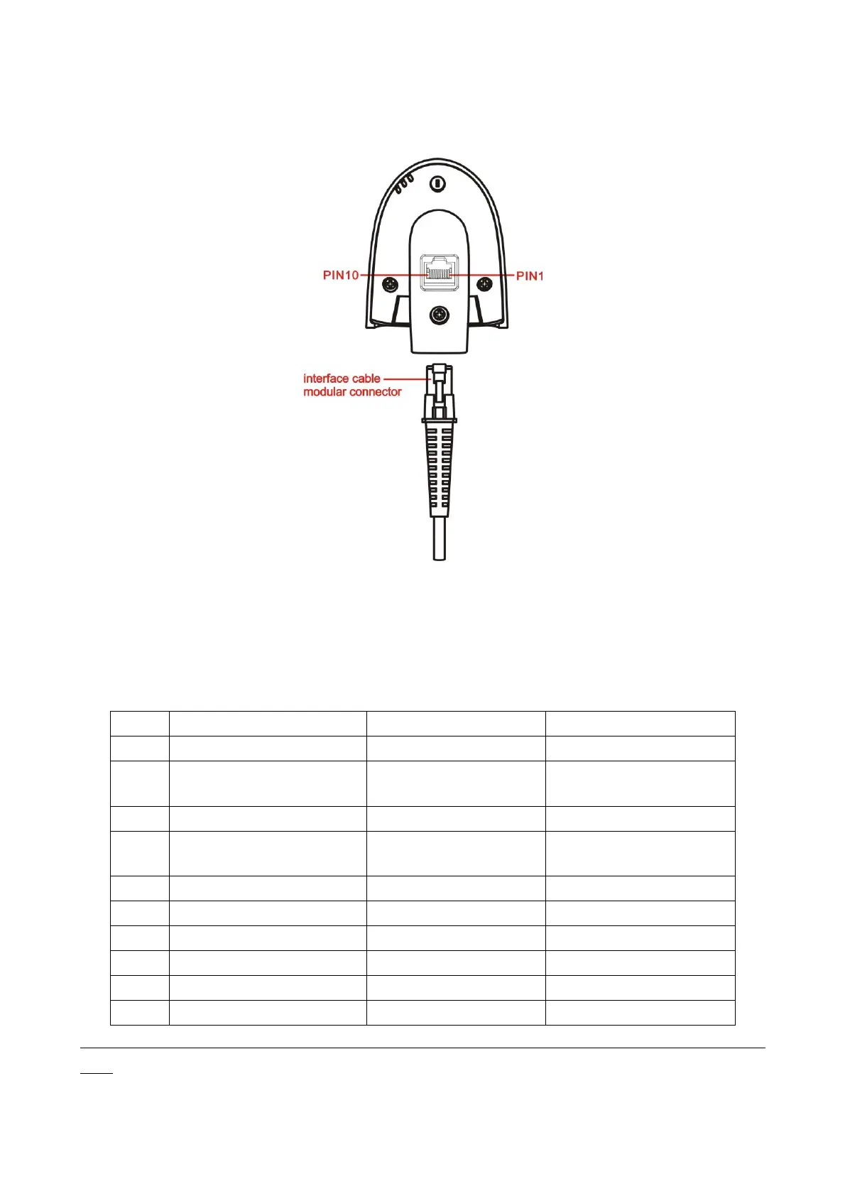
2-1 Cable connector pin-outs descriptions
Figure 2-1 Cable connector interface pin-outs
The pin-outs descriptions in Table 2-1 apply to the cable connector on the scanner and are for reference
only.
Table 2-1 Cable connector pin-outs descriptions
+3.3V ( for interface auto
selection purpose)
Ground (for interface auto
selection purpose)
+3.3V ( for interface auto
selection purpose)
+3.3V ( for interface auto
selection purpose)
Ground (for interface auto
selection purpose)
Note: Voltage level of all RS232 Pin-outs (RxD, TxD, CTS and RTS) is 0V for logic low and 3.3V for logic
high.