22
3-5 Distributed coordination wireless communication setting
3-5-1 Cluster establishment example
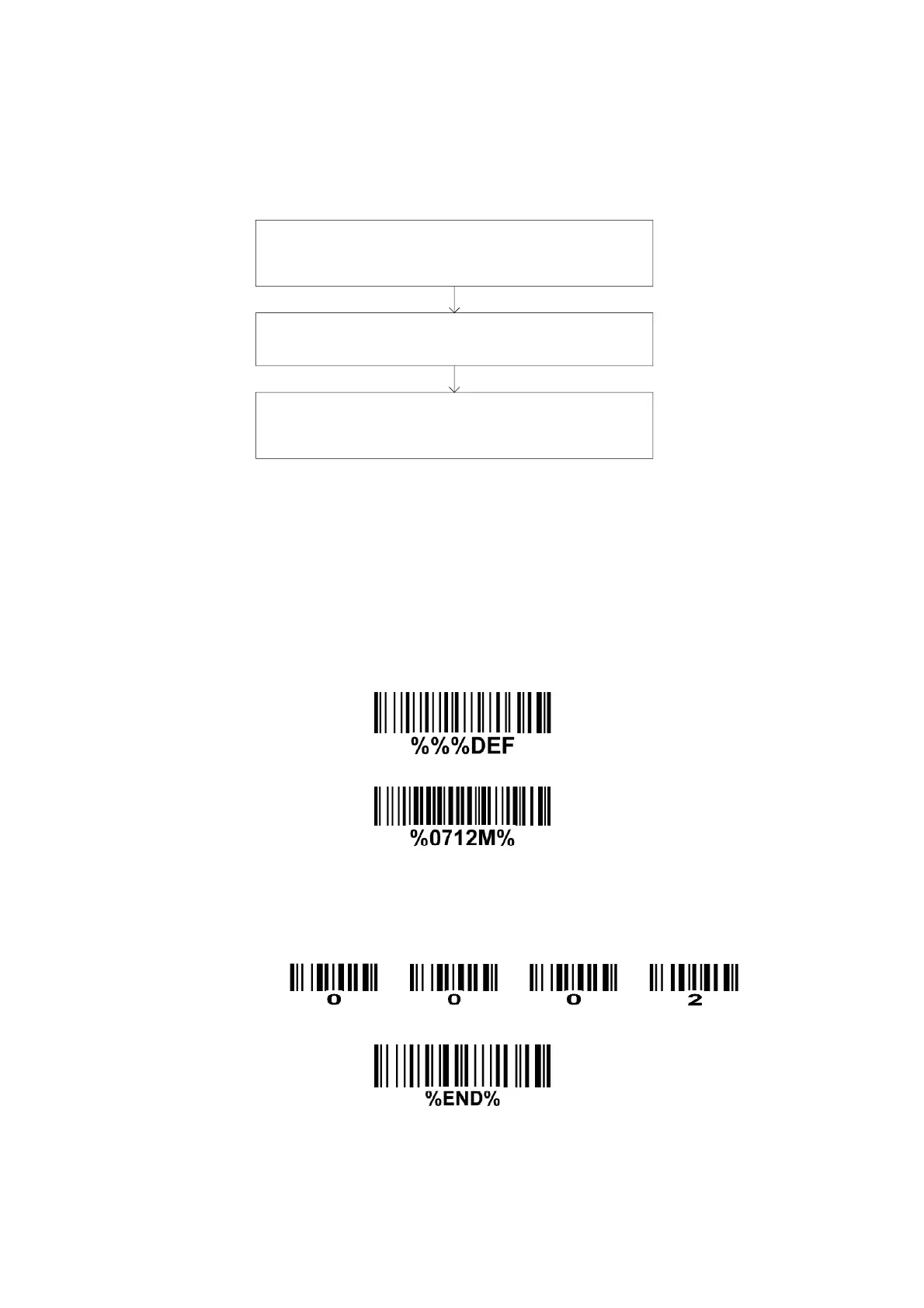
1.0 The flow chart of the general architecture of establishing a cluster is shown below.
Set RF channel No. (0701) and address (0712) for the first
handheld unit. Note that this channel No. is the channel
No. for this cluster.
By BIND operation, the cradle acquires the RF channel
No. of the cluster from the first handheld unit.
Set the addresses for other handheld units in the cluster.
By JOIN operation, all the following handheld units acquire
the RF channel No. of the cluster from the cradle.
1.1 Establish the wireless link between the cradle and the first handheld unit.
Step 1.0 Please refer to 8 Return default parameters and 9 Display firmware version & radio
communication setting to check the current wireless network topology. If it is point coordination
network topology, please scan the optional barcode 0700 and 0800 to change the network
topology.
Step 2.0 Scans the following barcode to return to default parameters.
This step can be omitted.
Step 3.1 Scan the following barcode to assign an address to a handheld unit.
Step 3.2 Scan four digits as an address.
All handheld units used in the same area must have different addresses.
Four digits for the handheld unit address(From 0000 to 1999)
For example:
Step 3.3 Scan the following barcode to complete the configuration.
Step 4.0 Scan the following barcode to bind the handheld unit with the cradle.
The blue LED on the handheld will blink to indicate that the handheld unit is ready to be
positioned onto the cradle.