Do you have a question about the Thermador PDR366 and is the answer not in the manual?
Details on finding the appliance's serial and data sticker.
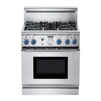
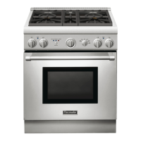
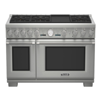
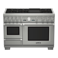
Lists and identifies key components of PDR models.
Identifies specific components of the electric oven section.
Explains the meaning of warning and caution symbols used in the manual.
Provides critical safety warnings and instructions for handling the appliance.
Outlines what Thermador will pay for and what is not covered under warranty.
Provides instructions on contacting Thermador for service inquiries.
Key considerations and warnings before installing the appliance.
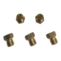
Instructions to verify the correct gas type for installation.
Guidance on choosing appropriate hood and blower models for installation.
Specifies hood placement height and recommends make-up air considerations.
Details required clearances and backguard/trim needs based on installation type.
Illustrates the gas and electrical supply zones for PDR dual-fuel models.
Details required clearance for junction box connections to the rear of the unit.
Provides shipping weights and doorway clearance requirements for moving.
Instructions for removing shipping bolts and the front kick panel.
Details on preparing holes and fastening the anti-tip bracket to various surfaces.
Steps for securing the floor-mounted anti-tip bracket.
Specifies pressure and connection requirements for natural gas.
Specifies pressure and connection requirements for propane gas.
Special requirements for installations in Massachusetts.
Requirement for shutoff valve and connecting flexible gas line.
Details required electrical supply specs and wire rating/size.
Precautions during gas supply piping system pressure testing.
Instructions for 4-conductor cord connection and hard-wiring.
Instructions for connecting the unit using a 3-conductor cord kit.
Detailed steps for connecting 3-wire and 4-wire power supplies.
Explains when and how to install backguards or island trims.
Lists available backguard kit model numbers for different installations.
Steps for hinge installation and door height adjustment.
Burner adjustment cautions and proper flame height guidelines.
Recommendations for cleaning stainless steel exterior surfaces.
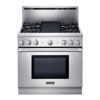
Lists and identifies the main components of the cooktop section.
Explains gas flow for sequenced and non-sequenced burners.
Describes key gas system components like regulators and manifolds.
Details electrical components like spark switches, solenoids, and indicator lights.
Describes electronic components such as the spark module and igniters.
Lists and identifies the main components of the oven section.
Identifies components located on the top of the oven assembly.
Lists and illustrates components found inside the oven cavity.
Explains the function and operation of the microprocessor-based control board.
Describes the oven selector, temperature gauge, lights, and variable resistor.
Details switches, cooling fans, and heating elements in the oven.
Indicates element on-time in seconds during 60-second cycles for various oven modes.
Describes the sequence of events for Bake and Convection Bake/Broil modes.
Lists error codes and their corresponding descriptions for system faults.
Explains how to interpret fault codes based on indicator light flashes.
Provides the main electrical wiring diagram for the PDR366 range.