Do you have a question about the Thermador PRG304 and is the answer not in the manual?
Identifies all-gas and dual-fuel models covered.
Emphasizes compliance with local codes for installation.
Details natural gas, propane gas, and electrical supply requirements.
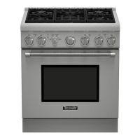
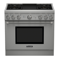
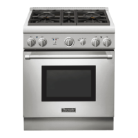
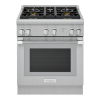
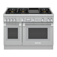
Describes various Thermador Professional Range configurations and features.
Provides critical safety warnings and emergency procedures for gas leaks.
Covers risks from incorrect installation, gas connection safety, and proper use.
Warns about the danger of the range tipping over and the need for an anti-tip device.
Advises on preventing property damage during installation, especially with walls/floors.
Details risks of electrical shock during installation and drilling.
Guides on selecting appropriate Thermador hoods and blowers for different range sizes.
Specifies hood placement height and the importance of make-up air.
Details required clearances around the range and overhead cabinets.
Illustrates the placement zones for gas and electrical supply connections.
Provides shipping weights, handling recommendations, and doorway clearance.
Instructions for removing parts like the door, kick panel for easier handling.
Guidance on using a dolly and positioning the range.
Instructions for adjusting the griddle to ensure it is level and stable.
Reinforces the warning about range tipping and the necessity of the anti-tip device.
Alerts to electrical shock risks when drilling for installation.
Lists parts and shows mounting kits for PRG All-Gas ranges.
Lists parts and shows mounting kits for PRDS Dual-Fuel ranges.
Details wall mounting locations and clearances for PRG ranges.
Details floor mounting locations for PRG ranges.
Details wall mounting locations and clearances for PRDS ranges.
Details floor mounting locations for PRDS ranges.
Instructions on verifying gas type and obtaining conversion kits for propane.
Specifies natural gas inlet connection and pressure requirements.
Specifies propane gas inlet connection and pressure requirements.
Details voltage, amperage, and frequency for different models.
Specifies wire size and temperature rating requirements for power supply.
Describes connecting with a 3-conductor cord and NEMA 10-50R receptacle.
Describes connecting with a 4-conductor cord and NEMA 14-50R receptacle.
Details how to connect a 3-wire power supply to the terminal block.
Details how to connect a 4-wire power supply, including grounding.
Explains the recommended grounding method for all-gas models using a 3-prong plug.
Explains grounding methods for dual-fuel models with 3 or 4 conductor power supplies.
Instructions for removing insulation and retainer on PRDS models before backguard installation.
Details how to attach the backguard to the range.
Guides on checking burner ignition, flame color, and stability.
Explains how to adjust air shutters for optimal flame on specific components.
Illustrates proper flame heights and appearance for various burners.
Provides instructions on cleaning and protecting the exterior surfaces of the range.
A comprehensive checklist for final installation verification.
Verifies gas supply connections, shut-off valve, and pressure.
Verifies electrical connections, grounding, polarity, and burner operation.
The provided manual describes the Thermador Professional Ranges, which are free-standing cooking appliances available in both all-gas and dual-fuel configurations. These ranges are designed for residential use and come in various models, including PRG304, PRG36, PRG48 (all-gas), and PRDS304, PRDS36, PRDS48 (dual-fuel).
These ranges serve as primary cooking appliances, offering multiple cooking zones and oven capabilities.