1here
are
two
types of connection for
the
Torch Leads.
One
type uses the Thermal Dynamics ATC connector. The
other
uses
02B
connections for gas
and
circuitry. Both
types require
an
adapter
kit
sold
separately.
ATC Connectors
Follow the instructions
provided
with
the
adapter
kit to
connect the
adapter
to
the
power
supply.
Inspect the halves of the ATC Connector. Align
the
male
connecto.r wi.th
the
female
receptacle
and
push
them
tagether
by
hand
until
they
seat
fully. Turn
the
Locking
Ring until
it
pulls
the
halves
of the connecto.r
tagether
fully.
Do
not
use
tools
to
tighten
the
connector.
If
there
is
any
resistance to
the
ring
tuming,
pull the halves of the
connector
apart,
realign
the
inner
components,
ensure
that
the
threaded
components
are aligned,
and
push
the
halves of
the
connector together again.
028
Connectors
Leads
with
02B
connectors are connected
to
the
power
supply
using
adapter
kits
sold
separately. Follow
the
instructions
provided
with
the
adapter
kit to connect
the
gas
and
electricallines to the
power
supply.
The
new
SL60QDTM
(Quick Disconnect) torch allows
for a
quick
change of
the
torch
handle
assembly from
the
leads.
To
change
the torch
handle
assembly
do
the
following.
1.
Remove
the
torch
handle
assembly
by
grasping
the
torch
handle
in
one
hand
and
the
coupler
nut
and
leads
in
the
other.
2.
Rotate the
nut
a
minimum
of
one
full
turn
to the
left (counter clockwise)
and
pull the torch
handle
assembly
out
from
the
leads
in
a straight line.
3.
To
reattach,
grasp
both
as
before
and
carefully
align
the
intemal
connecting parts.
4.
Carefully press
the
two
tagether
in
a straight line.
5.
Align
the
mark
on
the
coupler
nut
with
that
on
the
top
of
the
torch
handle
and
rotate to
the
right
( clockwise)
drawing
the
two
tagether
and
seating
the connections inside. Do
not
use tools to tighten.
The
parts
kit
provided
with
the torch
indudes
an
adhe-
sive label. Select
the
small
perforated
section
showing
the
appropriate
pressure setting for the
amperage
output
and
Ieads
length
tobe
used
with
this torch. Refer
to
the
charts.
Apply
this section
in
the
'Gas Supply' area
of
the
labelund
er
the
'Recommended
Operating
Pressure' text.
Discard
any
pressure setting sections
of
the
label
that
will
not
be
used.
Apply
the
large label
to
the
power
supply,
where
the
operator
can
see it for
easy
reference.
Refcr
to
the
Consumablcs
Selection
Chart
for
the
various
torch
parts
for
the
application
and
operation.
WARNING
Disconnect
primary
power
to
the
system
before
disassem-
bling
the
torch
or
torch
Ieads.
00
NOT
touch
any
internal
torch
parts
while
the AC indi-
cator light of the
Power
Suppl
y
isON.
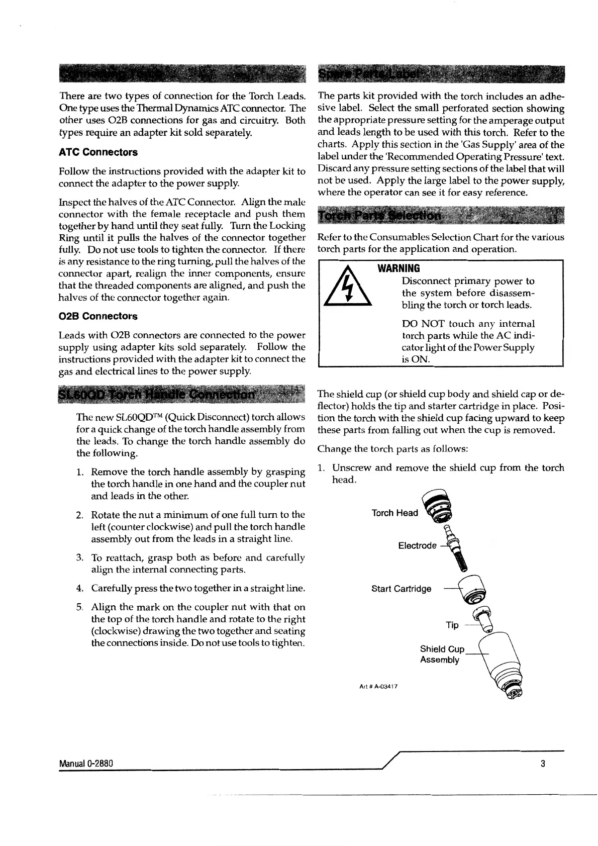
The
shield
cup
(or shield
cup
body
and
shield
cap
or
de-
t1ector)
holds
the tip
and
starter
cartridge
in
place. Posi-
tion the torch
with
the shield
cup
facing
upward
to
keep
these
parts
from falling
out
when
the
cup
is removed.
Change
the torch
parts
as follows:
1. Unscrew
and
remove
the
shield
cup
from the
torch
head.
TorchHead
~
Electrode \
Start Cartridge
~
Art#
A·03417
Tip
-~
Shield Cup
Assembly
~M~an~u~ai~0~-2~8~80~--------------------------------------~~
3
 Loading...