Electric boilers MINI BTH Installation & Operating Manual (Revision: May 2015), 10
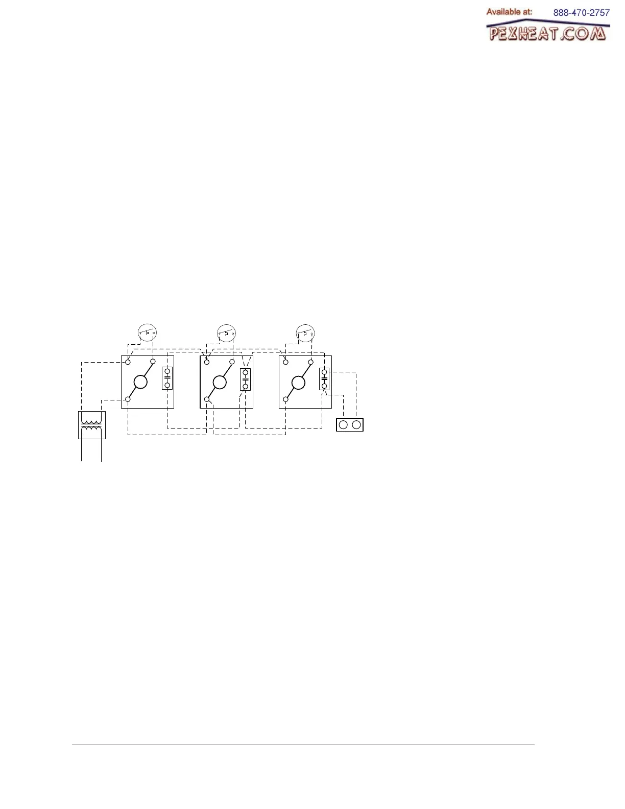
Zoning applications with motorized valves
Connect the end switch contact of all motorized
valve to terminals R & W on the boiler.
Connect the circulator to terminals “P1-P2 in the
boiler.
The connection of the thermostats to their
corresponding zone valve shall be done
according to the zone valve manufacturer’s
instructions. See on fig.5 below a typical
example.
The R & C terminals on the boiler can be used
to supply 24Vac to the zone valves if the
corresponding load does not exceed 30VA
otherwise an external transformer will be
required.
Voltage at the outlet of the transformer shall
never be under 24Vac.
Diagramme électrique/ Wiring diagram
Raccordement de zone valves/ Wiring for zoned valves system
1
2
1
2
1
2
Thermostat
Zone 1
120 V
24 Vac
Zone
valve
Thermostat
Zone 2
Thermostat
Zone 3
Zone
valve
Zone
valve
Transformateur/
Transformer
Moteur/
Motor
Moteur/
Motor
Moteur/
Motor
W
R
Terminaux
chaudière électrique
« BTH Mini »
Terminals
Electric boiler
Zone
valve
Interrupteur/
End switch
Interrupteur/
End switch
Interrupteur/
End switch
M
M M
Figure 6 : Zoning with Motorized valves