Do you have a question about the Thermo Scientific HAAKE RotoVisco 1 and is the answer not in the manual?
| Brand | Thermo Scientific |
|---|---|
| Model | HAAKE RotoVisco 1 |
| Category | Measuring Instruments |
| Language | English |
Explains symbols used in the instruction manual for user guidance and warnings.
Describes symbols found directly on the unit for operational and safety information.
Details the meaning and implications of the CE marking on the product.
Explains compliance with the Waste Electrical & Electronic Equipment Directive.
Outlines the company's commitment to ISO 9001:2008 quality management standards.
Provides contact information for inquiries and support in Germany and internationally.
Specifies maintenance intervals required to maintain warranty validity and recommended service procedures.
Provides critical safety instructions and warnings for proper and safe operation of the rheometer.
Details procedures for handling transportation damage and lists standard accessories included in the delivery.
Describes various sensor systems available for rheometers and their suitability.
Lists accessories like hoses and nozzles required for temperature control units.
Mentions the HAAKE RheoWin software for instrument control and data analysis.
Specifies recommended space, layout, mains connection, and fuse insertion for installation.
Explains cooling air needs for measuring heads and specifications for air supply.
Recommends oil-free compressors and specifies environmental conditions for testing.
Explains basic rheological measurement principles (CR vs. CS modes) and CS mode benefits.
Details measurement modes like Thixotropy, Time Curve, Temp. Programs, and Yield Point.
Describes measurement capabilities including Flow Curves, Time Curves, Temp. Programs, Viscoelasticity.
Lists and describes various temperature control units and their temperature ranges.
Highlights key features like quick-fitting sensors, controlled lift, and software capabilities.
Guides on unpacking, placing, and leveling the rheometer using its adjustable feet and spirit level.
Explains how to connect the instrument, control unit, PC, and printer via RS232 and other interfaces.
Details the PT100 sensor connections (input and output) for specific temperature control units.
Provides instructions on connecting hoses for liquid temperature control units, including flow direction.
Specifies the connection for cooling air required for the air bearings of RheoStress1 models.
Presents a table showing the compatibility of temperature control units with HAAKE RotoVisco1 and RheoStress1.
Describes the purpose and installation of the external filter for protecting temperature control units.
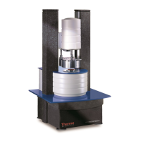
Identifies front-panel components of the measuring instrument without a temperature control unit.
Identifies rear-panel connections like power, RS232, printer, cooling air, and PT100.
Identifies front-panel components of the measuring instrument with a TCL/Z temperature control unit.
Identifies rear-panel connections for the instrument with TCL/Z unit.
Identifies front-panel components for instruments with specific temperature control units.
Identifies rear-panel connections for instruments with TCL/P, TCE/P, TCP/P, TCP/PE units.
Identifies front-panel components of the unit with TCE/PC stabilization and cone heater TC1.
Identifies rear-panel connections for the unit with TCE/PC stabilization and cone heater TC1.
Identifies front-panel components of the instrument with SHRP temperature control unit.
Identifies rear-panel connections for the instrument with SHRP temperature control unit.
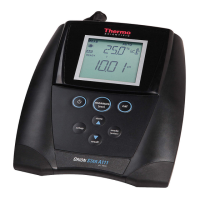
Explains the functions of the display unit, including header, keys, and general screen layout.
Describes diagnostic functions and how to set the date and time via the display unit.
Covers display contrast, unit switching, country settings, and online value/graph configuration.
Explains how to access and manage stored measurement data.
Guides on navigating display unit menus and controlling the instrument's lift mechanism.
Describes defining and selecting operator, sample names, and batch IDs within the interface.
Guides on setting up measurement sequences, defining jobs, and initiating tests.
Provides step-by-step instructions for powering on the rheometer and initial device checks.
Guides on navigating the display unit menus, starting with the Configuration submenu.
Provides instructions for launching the RheoWin software and connecting to the measuring device.
Explains the "Upload Mode" for operating the device independently of the PC for programming or data transfer.
Explains torque compensation and inertia correction for accurate measurement results.
Details data upload, communication records, and managing user/sample/sensor data.
Describes creating measurement procedures (JOBS) and uploading them to the device.
Describes viewing, printing, and importing measurement results into RheoWin.
Describes the quick cut-off switch and its function to interrupt measuring jobs, drive, and heating.
Explains the function of the TCO unit, measurement of torque, and temperature calculation.
Details the TCL/Z unit, beaker insertion, hose connections, and circulator placement.
Describes the TCL/P unit, its plate, temperature ranges, and high-temperature measurement recommendations.
Explains the TCE/P unit, its plate, temperature ranges, and the role of the solenoid valve in cooling control.
Describes TCP/P and TCP/PE units using Peltier elements for temperature control.
Explains the Peltier process, cooling coil operation, recommended liquids, and heating/cooling rates.
Details the TCE/P unit with TC1 for high-temperature measurements up to 350°C.
Explains the PID controller, independent heating elements, and use of ceramic shafts with TC1.
Describes the compressed air distributor setup, depending on building supply or HAAKE compressor.
Focuses on the SHRP unit for bitumen and asphalt testing, dynamic modes, and temperature ranges.
Introduces various cylinder sensor systems, including immersion discs, coaxial cylinders, and their standards.
Explains calculation factors, shear stress (τ) range, and shear rate (γ) range.
Details how to calculate the viscosity measuring range based on shear stress and shear rate ranges.
Describes Z-DIN cylinder systems for polymer dispersions, ease of cleaning, and suitability for temperature programs.
Provides geometric definitions and calculation equations for Z-DIN systems.
Lists detailed specifications and calculation factors for Z10DIN, Z20DIN, and Z34DIN sensors.
Presents shear stress, shear rate, and deformation calculation equations according to DIN 53019/ISO 3219.
Lists detailed specifications and calculation factors for Z31, Z38, and Z41 sensors.
Provides geometric definitions and calculation equations for Cylinder System Z sensors.
Describes the DG43 sensor for low viscous liquids and small volumes, noting its double shearing surfaces.
Details the geometry and calculation equations for the DG43 double gap cylinder sensor.
Lists detailed specifications and calculation factors for the DG43 sensor.
Shows the solvent trap accessory for specific cylinder sensor systems.
Shows the solvent trap accessory for the Z43 cylinder sensor.
Discusses the application of cone-plate and plate-plate sensors for viscous liquids and precision measurements.
Highlights cone radius and cone angle as key characteristics of cone-plate sensor systems.
Presents shear stress and shear rate calculation equations for cone-plate sensors.
Discusses common errors in cone/plate measurements, such as incorrect gap or filling.
Lists specifications and calculation factors for C20/0.5, C35/0.5, and C60/0.5 cone-plate sensors.
Lists specifications and calculation factors for C20/1, C35/1, and C60/1 cone-plate sensors.
Lists specifications and calculation factors for C20/2, C35/2, and C60/2 cone-plate sensors.
Lists specifications and calculation factors for C20/4, C35/4, and C60/4 cone-plate sensors.
Explains plate-plate sensor systems, determined by plate radius and variable distance.
Presents shear stress, shear rate, and deformation calculation equations for plate-plate sensors.
Discusses errors related to incorrect gap or filling in plate-plate sensor systems.
Explains graphical methods for determining the 'n' exponent in non-Newtonian flow behavior.
Lists specifications and calculation factors for PP20, PP35, and PP60 plate-plate sensors.
Describes specialized platter-platter geometries for tests with wall slip, and necessary software adjustments.
Explains the application of the HS system for high shear rate viscosity measurements and shear stability.
Lists specifications and calculation factors for HS25, HS100, and HS400 sensors.
Lists specifications and calculation factors for SHRP PP 1 mm plate-plate sensors.
Describes the FL system for measuring thixotropic substances like cremes and gels, preserving sample structure.
Provides a compatibility table for optional sensors with HAAKE RotoVisco1 and RheoStress1.
Warns about thermal expansion and its effect on measurements, suggesting solutions.
Illustrates the operational range limits for oscillation measurements with RheoStress 1.
Explains mechanical and electromagnetic influences on dynamic measurements and the need for corrections.
Details methods for accurately determining the mass moment of inertia of the sensor system.
Provides essential care instructions, including avoiding impacts, cable care, and cleaning precautions.
Outlines the annual system check and recommended maintenance tasks for the RheoStress1.
Lists the annual system check and recommended maintenance tasks for the Rotovisco1.
Explains the filter unit's connection to the air supply and the procedure for filter replacement.
Details the procedure for changing or cleaning the flat sieve in the tempering unit.
Advises against opening the unit and directs users to the Thermo Fisher Scientific service department.
Describes the pin assignments for connecting the rheometer to a computer via RS232.
Details the pin assignments for the Centronics printer connection.
Lists pin assignments for connecting the optional display unit.
Explains PT100 sensor connections for TCO, TCL/P, and TCL/Z units.
Emphasizes using shielded cables and proper shielding contact for EMC requirements and PT100 sensor wiring.
Lists key technical specifications like torque, speed, frequency, and bearing type for RV1 and RS1 models.
Provides physical dimensions, weight, mains voltage, frequency, and fuse ratings for various configurations.
Categorizes measurement modes (CD, CR, CS) and describes their application in rheological testing.
Classifies steady rotation measurements into Creep/Recovery, Stress Growth/Decay, and Ramps.
Explains oscillation measurements for determining elastic and viscous properties, including moduli.
Defines common viscosity behaviors like Newtonian, Pseudoplastic, Dilatant, Thixotropic, Rheopectic, and Plastic.
Lists typical instrument, measuring, rheometrical, and rheological quantities and parameters.