EasyManua.ls Logo

Thermokon LCF02 5DO RS485 Modbus - User Manual

Thermokon LCF02 5DO RS485 Modbus
12 pages
Print Icon
To Next Page IconTo Next Page
Loading...
» LCF02 5DO RS485 Modbus
Fancoil controller (flush mounting)
valid from version 1.0.C
Thermokon Sensortechnik GmbH, Platanenweg 1, 35756 Mittenaar, Deutschland · tel: 02778/6960-0 · fax: -400 · www.thermokon.de · email@thermokon.de
LCF02-5DO_Datasheet_en.docx © 2021
Datasheet
Subject to technical alteration
Issue date: 06.04.2021 • A114
» APPLICATION
The fancoil room controller has been designed for individual control of temperature in commercial, industrial and residential buildings. It is tailored
for two-pipe fan coil with two-wire electric valves. With its flush mounted modern design the device combines digital technology with a large LCD
display and additional buttons, which enables the single room controller to be used intuitively.
» SECURITY ADVICE CAUTION
The installation and assembly of electrical equipment should only be performed by authorized personnel.
The product should only be used for the intended application. Unauthorised modifications are prohibited! The product must not be
used in relation with any equipment that in case of a failure may threaten, directly or indirectly, human health or life or result in
danger to human beings, animals or assets. Ensure all power is disconnected before installing. Do not connect to live/operating
equipment.
CAUTION! Risk of electric shock due to live components within the enclosure, especially devices with mains voltage
supply (usually between 90..265 V).
Please comply with
Local laws, health & safety regulations, technical standards and regulations
Condition of the device at the time of installation, to ensure safe installation
This data sheet and installation manual
» NOTES ON DISPOSAL
As a component of a large-scale fixed installation, Thermokon products are intended to be used permanently as part of a building
or a structure at a pre-defined and dedicated location, hence the Waste Electrical and Electronic Act (WEEE) is not applicable.
However, most of the products may contain valuable materials that should be recycled and not disposed of as domestic waste.
Please note the relevant regulations for local disposal.
Question and Answer IconNeed help?

Do you have a question about the Thermokon LCF02 5DO RS485 Modbus and is the answer not in the manual?

Thermokon LCF02 5DO RS485 Modbus Specifications

General IconGeneral
BrandThermokon
ModelLCF02 5DO RS485 Modbus
CategoryMeasuring Instruments
LanguageEnglish

Summary

APPLICATION

Product Application Description

Describes the fancoil room controller's purpose for individual temperature control in buildings.

SECURITY ADVICE - CAUTION

General Electrical Safety

Installation and assembly by authorized personnel only; use for intended application.

Risk of Electric Shock

Caution regarding live components and mains voltage supply.

Compliance Requirements

Adherence to local laws, health & safety regulations, and technical standards.

NOTES ON DISPOSAL

Disposal Context and Recycling

Products are permanent installations; WEEE not applicable, recycling encouraged.

REMARKS TO ROOM SENSORS

Location and Accuracy

Proper mounting location is crucial for accurate room temperature measurement and air circulation.

Mounting Surface Influence

Wall thermal characteristics affect measurement; flush mounting has longer response time.

TECHNICAL DATA

Core Technical Specifications

Details measuring values, output contacts, network, power, and temperature specs.

Input and Control Specifications

Covers device inputs, control functions, display, enclosure, and connections.

Environmental and Mounting Specs

Specifies ambient conditions, weight, and mounting method.

PRODUCT TESTING AND CERTIFICATION

Declaration of Conformity

Confirms declaration of conformity is available on the manufacturer's website.

CONNECTION PLAN

Power Supply Connection Details

Explains 24 V AC/DC power supply connection and polarity importance.

DISPLAY PANEL OVERVIEW

Display Indicators and Symbols

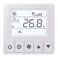
Details various indicators for fan speed, modes, temperature, errors, and status.

FUNCTION DESCRIPTION

Modbus Communication Settings

Details Modbus interface, protocol, baud rate, parity, data, and stop bits.

Parameter Table Access and Operation

Explains how to enter and navigate the parameter table using device buttons.

Control Logic and Modes

Describes 2-point/3-point and PI control modes for heating and cooling.

OPERATING MODES

Standby, ECO, and ON States

Details the device's power states: Standby, ECO mode, and ON, including transitions.

Temperature Sensor and Limit Functions

Covers using temperature sensor inputs for sensing, limiting, and change-over.

Fan Control Logic and Auto Mode

Explains fan speed control based on mode, stage, and temperature difference.

OPERATING SETTINGS AND ALARMS

Temperature Units and Offset

Switching units (°F/°C) and correcting internal/external sensor offsets.

Setpoint Range, Key Lock, and Power Loss

Adjusting setpoint limits, locking keys, and configuring power failure behavior.

Input Integration (Occupancy, Window, ESI)

How occupancy, window contact, and ESI inputs affect operation.

Sensor Failure and Alarm Management

Handling sensor failures, displaying errors, and manual control options.

INPUT REGISTER DESCRIPTIONS

Model and Firmware Info

Provides device model identification and firmware version.

Sensor and Status Readings

Details readings for integrated/external sensors, fan status, and VA outputs.

Failure and Input Status

Lists failure codes and configurations for external inputs 1 and 2.

HOLDING REGISTERS - GENERAL SETTINGS

Device Identification, Display, and Power

Settings for device location, LCD unit, beeper, backlight, and power failure behavior.

Sensor Offset, Language, Password, and Limits

Correction for sensor offsets, language, password setting, and external temp limits.

Key Lock and Display Configuration

Configuring key lock functionality and various display settings.

HOLDING REGISTERS - SET POINT SETTINGS

Setpoint Limits, Adjustment, and ECO Modes

Setting setpoint limits, adjustment steps, and ECO mode temperature targets.

HOLDING REGISTERS - PI CONTROLLER SETTINGS

Fan Coil Type and Fan Control

Selecting fan coil type and configuring fan stages/operation modes.

Control Loop Parameters (Heating;Cooling)

PI controller parameters like proportional band and integration time for heating/cooling.

Thresholds and Protection Settings

Fan stage thresholds, frost protection, and change-over temperature settings.

Valve Control and Deadband

Configuration for valve types, deadband, and PWM cycle time.

HOLDING REGISTERS - INPUT CONFIGURATION

External Input 1 Configuration

Lists and describes functions for external input 1, e.g., occupancy, window contact.

External Input 2 and Sensor Input Config

Covers configuration for external input 2 and the main sensor input.

Energy Saving and Occupancy Delays

Settings for Energy Savings Input ON delay and Occupancy Input OFF delay.

HOLDING REGISTERS - MODBUS OVERRIDE

Modbus Override: Fan Speed and Setpoint

Allows overriding fan speed and setpoint temperature via Modbus.

Modbus Override: Controller Modes and Symbols

Allows overriding controller modes (Comfort/ECO) and active display symbols via Modbus.

MOUNTING ADVICE AND DIMENSIONS

Installation Safety and Wall Mounting

Emphasizes disconnecting power and provides instructions for wall mounting the base plate.

Assembly and LCD Protection

Instructions for attaching the base plate and front cover, and protecting the LCD.