The ThermoTec Mini Swimming Pool Heat Pump is designed to efficiently heat swimming pool water and maintain a constant temperature. This manual provides comprehensive information for installation, debugging, discharge, and maintenance.
Function Description
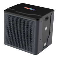
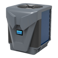
The ThermoTec Mini is a swimming pool heat pump that utilizes a heat exchanger to transfer heat from the ambient air to the pool water. It is designed for outdoor installation and operates quietly due to its efficient rotary/scroll compressor and low-noise fan motor. The unit incorporates micro-computer controlling, allowing users to set all operation parameters and view the status on an LCD wire controller.
Important Technical Specifications
The ThermoTec Mini heat pump is available in two models: 4kW and 5kW, both using R32 refrigerant.
Performance Data (27/24.3°C ambient, 26°C inlet water):
- Thermotec Mini 4kW:
- Heating capacity: 4 kW (13648 Btu/h)
- Heating Power Input: 0.8 kW
- COP: 5.0
- Thermotec Mini 5kW:
- Heating capacity: 5 kW (17060 Btu/h)
- Heating Power Input: 0.98 kW
- COP: 5.10
Performance Data (15/12°C ambient, 26°C inlet water):
- Thermotec Mini 4kW:
- Heating capacity: 2.7 kW (9212 Btu/h)
- Heating Power Input: 0.73 kW
- COP: 3.7
- Thermotec Mini 5kW:
- Heating capacity: 3.3 kW (11260 Btu/h)
- Heating Power Input: 0.89 kW
- COP: 3.3
General Specifications (for both models):
- Power Supply: 220~240V~/50Hz
- Compressor Quantity: 1 (rotary type)
- Fan Number: 1
- Fan Power Input: 25 W
- Fan Rotate Speed: 800 RPM
- Fan Direction: Horizontal
- Noise: 49 dB(A) (4kW), 50 dB(A) (5kW)
- Water Connection: 32 mm
- Water Flow Volume: 1.2 m³/h (4kW), 1.8 m³/h (5kW)
- Water Pressure Drop (max): 1.8 kPa (4kW), 2.8 kPa (5kW)
- Unit Net Dimensions (L/W/H): 420 x 350 x 380 mm
- Unit Ship Dimensions (L/W/H): 450 x 420 x 400 mm
- Operating range (Ambient temperature): -7°C to 43°C
- Operating range (Water temperature): 15°C to 44°C
- Heat exchanger: PVC & Titanium tube (single wall, not suitable for potable water connection)
Electrical Wiring (Cable Specification - Single Phase Unit):
- For currents up to 10A: Phase line 2x1.5mm², Earth line 1.5mm², MCB 20A, Creepage protector 30mA less than 0.1 sec.
- For currents 10-16A: Phase line 2x2.5mm², Earth line 2.5mm², MCB 32A, Creepage protector 30mA less than 0.1 sec.
- For currents 16-25A: Phase line 2x4mm², Earth line 4mm², MCB 40A, Creepage protector 30mA less than 0.1 sec.
- For currents 25-32A: Phase line 2x6mm², Earth line 6mm², MCB 40A, Creepage protector 30mA less than 0.1 sec.
- For currents 32-40A: Phase line 2x10mm², Earth line 10mm², MCB 63A, Creepage protector 30mA less than 0.1 sec.
- For currents 40-63A: Phase line 2x16mm², Earth line 16mm², MCB 80A, Creepage protector 30mA less than 0.1 sec.
- For currents 63-75A: Phase line 2x25mm², Earth line 25mm², MCB 100A, Creepage protector 30mA less than 0.1 sec.
- For currents 75-101A: Phase line 2x25mm², Earth line 25mm², MCB 125A, Creepage protector 30mA less than 0.1 sec.
- For currents 101-123A: Phase line 2x35mm², Earth line 35mm², MCB 160A, Creepage protector 30mA less than 0.1 sec.
- For currents 123-148A: Phase line 2x50mm², Earth line 50mm², MCB 225A, Creepage protector 30mA less than 0.1 sec.
- For currents 148-186A: Phase line 2x70mm², Earth line 70mm², MCB 250A, Creepage protector 30mA less than 0.1 sec.
- For currents 186-224A: Phase line 2x95mm², Earth line 95mm², MCB 280A, Creepage protector 30mA less than 0.1 sec.
- Signal line: n×0.5mm²
Usage Features
Installation:
- The unit should be installed outdoors, within 2.5 meters of the pool to minimize heat loss from hoses.
- It requires fresh air, electricity, and a water supply.
- Avoid enclosed areas or placing the unit where expelled air can recirculate.
- Plumbing involves connecting the unit in the pool pump discharge (return) line, downstream of the filter and circulation pump, but upstream of any chlorinators, ozonators, or chemical pumps.
- The unit is supplied with an inline RCD and UK plug. An all-pole disconnection device with at least 3mm clearances in all poles and a leakage current not exceeding 10mA (RCD with rated residual operating current not exceeding 30mA) must be incorporated into the fixed wiring.
- The appliance must be stored in a room without continuously operating ignition sources and with a floor area larger than 30m².
Initial Start-up:
- Turn on the pool circulation pump and check for water leaks.
- Turn on the electrical power supply, press the reset button on the RCD, then press the ON/OFF button on the display panel.
- After a few minutes, the air leaving the fan should be cooler (5-10°C below ambient).
- The unit will automatically turn off if the filter pump is off.
- Allow the unit and pool pump to run 24 hours a day until the desired pool water temperature is reached. The unit will slow down and turn off when the water-in temperature reaches the set point and is maintained for 45 minutes. It will restart automatically when the pool temperature drops more than 0.5°C below the set temperature.
- Time Delay: A 3-minute built-in solid-state restart delay protects control circuit components and prevents restart cycling.
- Water Flow Switch: The unit is equipped with a water flow switch that turns on the heat pump when sufficient water flow is detected. An E03 error message indicates insufficient water flow.
Wire Controller Operation:
- ON/OFF: Press and hold the ON/OFF key for 0.5-5 seconds to turn the unit on or off.
- Setting Desired Water Temperature: In either ON or OFF mode, press the Up or Down button once to view the set point, then press again to adjust it. Settings are saved automatically after 3 seconds of no button press. Short presses change the value by 0.5°C/1°F, while long presses change it by 1°C/1°F.
- Mode Setting: In the main interface, press and hold Up and Down for 0.5 seconds to enter mode setting. Use Up or Down to switch between cooling, heating, and auto modes. The system memorizes the current mode after 5 seconds of no operation.
- Malfunction Display: Error codes are shown on the controller screen. Multiple errors can be viewed by pressing Up or Down. The unit returns to malfunction display after 20 seconds of no operation in the main interface.
Bluetooth Operation (Aqua Temp App):
- Account Login: Register an account using an email address and password. A verification code is sent to the email for registration and password reset.
- Add Device: After logging in, add and bond the device through the "My Device" interface.
- Device Management: The app allows displaying current operating mode, adjusting target temperature, and viewing the latest 3-day weather forecast. "Parameter Settings" are for after-sales maintenance only.
Maintenance Features
General Maintenance:
- Water Supply: Regularly check water supply to avoid no water flow or air entering the system. Clean the pool filter regularly to prevent damage from clogged filters.
- Unit Area: Keep the area around the unit dry, clean, and well-ventilated. Clean the heat exchanger fins regularly to maintain good airflow.
- Refrigerant System: Only certified technicians should service the refrigerant system.
- Electrical: Frequently check power supply and cable connections. If the unit operates abnormally, switch it off and contact a qualified technician.
- Winterization: Disconnect hoses and drain all water from the heat pump to prevent freezing. Store the unit indoors in a dry building during winter. Damage from water freezing is not covered by warranty.
Safety Checks for Flammable Refrigerants (R32):
- No Ignition Sources: No person working on the refrigeration system should use ignition sources. Keep all ignition sources (including cigarette smoking) away from the work site. "No Smoking" signs must be displayed.
- Ventilated Area: Ensure the work area is open or adequately ventilated to safely disperse any released refrigerant.
- Refrigeration Equipment Checks: Electrical components must be of the correct specification. Follow manufacturer's guidelines. Check charge size, ventilation, secondary circuit for refrigerant presence, and legibility of markings. Ensure pipes and components are protected from corrosion.
- Electrical Device Checks: Perform initial safety checks (discharge capacitors, ensure no live components exposed, earth bonding continuity) and component inspection before connecting electrical supply.
- Repairs to Sealed Components: Disconnect all electrical supplies before removing sealed covers. If power is necessary, use a leak detection system. Ensure casing protection is not compromised.
- Intrinsically Safe Components: Only work on these components live in a flammable atmosphere if they are the only types that can be. Use correct test apparatus and manufacturer-specified parts.
- Cabling: Check for wear, corrosion, excessive pressure, vibration, sharp edges, or environmental effects.
- Detection of Flammable Refrigerants: Do not use potential ignition sources (e.g., halide torch, naked flame) for leak detection. Use electronic leak detectors calibrated to the refrigerant and set at 25% LFL maximum. Leak detection fluids are suitable, but avoid chlorine-containing detergents.
- Fire Extinguisher: Have a dry powder or CO2 fire extinguisher available for any hot work.
- Decommissioning: Follow a controlled procedure for refrigerant removal, purging with inert gas (OFN), evacuation, and recovery into designated cylinders. Label equipment as decommissioned and containing flammable refrigerant.
- Charging Procedures: Prevent contamination of different refrigerants. Keep hoses short. Keep cylinders upright. Earth the system. Label the system. Do not overfill. Pressure test with OFN before recharging and leak test after charging.
The safety wire model is 5*20_5A/250VAC and must meet explosion-proof requirements. For outdoor installations, use UV-resistant cables.