14
4.Use and Operation Instruction of Wire Controller
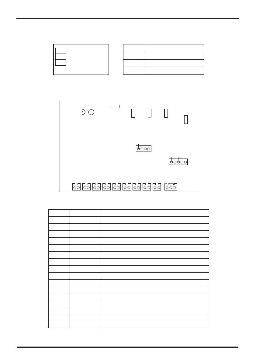
5.2 Controller interface diagram and definition
Connections explanation:
5. Interface diagram
5.1 Wire control interface diagram and definition
3.3V
NET
GND
Sign
Meaning
3.3V
NET
GND
3.3V(power +)
Communication signal
GND(power-)
T1
13
1
Fan motor(220-230VAC)
T6
No.
Symbol
Meaning
Compressor of system1(220-230VAC)
3-core communication
4
5
6
7
8
9
High pressure protection
Low pressure protection
2
Neutral wire
3
10
T2
11
Water outlet temperature(input)
Water inlet temperature(input)
Ambient temperature(input)
Coil temperature( input)
CN 1
JP 1
12
Exhaust temperature( )input
T5
T7
T8
T9
PGND1
RL 3
RL 2
RL 1
Grounding
Water pump/ 220-230VAC) 4-way valve(
T4
T3
CN 3
14
15
16
Live wire
Water flow switch
Reserve
13
T1
CN1
CN3
RL3
RL1
RL2
T3
T2
T1
T9
T8
T7T6
T5
T4
JP1
PGND1
MN1001
SWD_CLK
SWD_I0
GND
VCC
CN6
SWD_I0
SWD_CLK
VCC
GND
CN5
2
1
2
1
2
1
2
1
2
1
2
1
2
1
2
1
2
1 1
2 3