EasyManua.ls Logo

Thitronik WiPro III safe.lock - User Manual

Thitronik WiPro III safe.lock
13 pages
Print Icon
To Next Page IconTo Next Page
Loading...
1
Updated 05/22
WiPro III safe.lock
Installation Manual
Fiat Ducato 8
(Model year 2022+)
Disclaimer:
This installation manual is intended for
professional service companies. Appropri-
ate background knowledge about work on
vehicle electrics and electronics is there-
fore required.
Improper interventions into the vehicle
electronics and their components can un-
der certain circumstances cause them to
no longer function as intended. This can
considerably endanger the installer (work,
e.g., on the airbag system) and the road-
worthiness of the vehicle and can result
not only in property damage, but also in
personal injury.
Therefore, have all work on the vehicle
electronics carried out by a qualified shop.
Thitronik GmbH is not liable for damage to
property and/or personal injury resulting
from improper, incorrect or only partially
completed installation work. The installing
service company is obligated to ensure
that its connection work neither is faulty
in itself nor can lead to faults or dangers
on the vehicle.
The instructions in the WiPro installation
manual remain applicable. Unused inputs
and outputs must be isolated.
Should the given vehicle conditions differ
from those described herein, please con-
tact the manufacturer or our technical
support team.
Question and Answer IconNeed help?

Do you have a question about the Thitronik WiPro III safe.lock and is the answer not in the manual?

Summary

Manual Introduction and Disclaimer

Disclaimer and Purpose

States the manual's intended audience and liability.

Pre-Installation Vehicle Checks and Setup

Vehicle Condition Checks

Verifies vehicle compatibility and existing systems.

Required Tools and Aids

Lists tools and accessories needed for installation.

CAN Bus Interface Configuration

Setting the DIP switch for the Ducato CAN bus interface.

Dashboard and Computer Removal

Step 1: Remove Dashboard Panelling

Guide to removing dashboard panels.

Step 2: Dismantle On-Board Computer

Instructions for removing the on-board computer unit.

WiPro Unit and Earth Connection

Step 3: Adhere WiPro to On-Board Computer

Attaching the WiPro unit to the on-board computer.

Step 4: Electrical Connection to Earth

Connecting the earth wire to the vehicle chassis.

CAN, Lights, and Power Connections

Step 5: CAN & Flashing Lights Connection

Connecting to CAN bus and flashing warning lights.

Step 6: 12 V & Ignition Connections

Wiring for 12V power and ignition signals.

Central Locking and CAN-BUS Control

Step 7: Safe.lock Central Locking & CAN-BUS

Connecting for central locking and CAN bus control.

Central Locking Troubleshooting

Diagnosing common central locking system errors.

Horn, LED, and Wireless Accessories Setup

Step 8: Connect to Vehicle Horn

Wiring the WiPro to the vehicle horn.

Step 9: Install Status LED

Mounting and connecting the status indicator LED.

Step 10: Teach-in Wireless Accessories

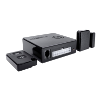
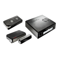
Pairing wireless accessories with the WiPro unit.

Final Installation Steps and Testing

Step 11: Mount Wireless Accessories

Installing additional wireless components.

Step 12: Final Function Test

Comprehensive testing of system functionality.

Troubleshooting Common Issues

Possible Mistakes and Solutions

Diagnosing and resolving system malfunctions.

Wireless Magnetic Contact Mounting

Mounting Overview and Item Numbers

Introduction to mounting wireless magnetic contacts.

Magnetic Contact Installation Details

Transmitter Housing Orientation

Correct positioning of transmitter housing variants.

Circuit Board Alignment Rule

Critical alignment of circuit board and LED for functionality.

Advanced Mounting and Fixing Options

Alternative Mounting Variants

Options for upright mounting on frames or panes.

Fixing Options for Magnetic Contacts

Methods for attaching magnetic contacts (adhesive/screw).

Circuit Board Alignment and Magnet Positioning

Circuit Board and Component Positions

Overview of circuit board layout in the transmitter housing.

Magnet Positioning for Reed Switch

Correct placement of the magnet relative to the reed switch.

Thitronik WiPro III safe.lock Specifications

General IconGeneral
CategoryAutomobile Accessories
TypeAlarm System
ModelWiPro III safe.lock
BrandThitronik
Power Supply12V DC
Operating Temperature-20°C to +60°C
FeatureWireless
Locking MechanismElectronic
CommunicationWireless

Related product manuals