EasyManua.ls Logo

Thitronik WiPro III + safe.lock - User Manual

Thitronik WiPro III + safe.lock
11 pages
Print Icon
To Next Page IconTo Next Page
Loading...
1
Disclaimer:
This installation manual is intended for
professional service companies. Appropri-
ate background knowledge about work on
vehicle electrics and electronics is there-
fore required.
Improper interventions into the vehicle
electronics and their components can un-
der certain circumstances cause them to
no longer function as intended. This can
considerably endanger the installer (work,
e.g., on the airbag system) and the road-
worthiness of the vehicle and can result
not only in property damage, but also in
personal injury.
Therefore, have all work on the vehicle
electronics carried out by a qualified shop.
Thitronik GmbH is not liable for damage to
property and/or personal injury resulting
from improper, incorrect or only partially
completed installation work. The installing
service company is obligated to ensure
that its connection work neither is faulty
in itself nor can lead to faults or dangers
on the vehicle.
The instructions in the WiPro installation
manual remain applicable. Unused inputs
and outputs must be isolated.
Should the given vehicle conditions differ
from those described herein, please con-
tact the manufacturer or our technical
support team.
Updated 12/20
WiPro III + safe.lock Installation Manual
Fiat Ducato X250
Euro 4 (2006–2011)
Question and Answer IconNeed help?

Do you have a question about the Thitronik WiPro III + safe.lock and is the answer not in the manual?

Summary

WiPro III + safe.lock Installation Guide

Teach-in Wireless Contacts

Procedure for teaching in wireless contacts and transmitters before installation.

Configure CAN Bus Interface

Setting the CAN bus interface for the Ducato vehicle type.

Remove Dashboard Panelling

Removing the dashboard panelling for installation access.

Prepare Power and On-Board Computer

Preparing for power connection and removing the on-board computer.

Connect Central Locking Wire

Connecting the safe.lock wire for the central locking system.

Connect CAN and Turn Signals

Connecting CAN bus and turn signal actuation wires.

Connect Horn Actuation

Connecting the horn actuation wire.

Install Ignition Connection

Connecting the ignition wire.

Install Status LED

Installing the status LED indicator.

Fix Mounting Plate

Fixing the mounting plate for the device.

Perform Function Test and Troubleshooting

Performing a function test and addressing possible faults.

Mounting Wireless Magnetic Contacts

Transmitter Mounting Variants

Different ways to mount transmitter housings on windows.

Door or Hatch Mounting

Ideal alignment and fixing for door or hatch mounting.

Fixing Options for Contacts

Methods for attaching magnetic contacts using adhesive or screws.

Circuit Board Alignment

Correct alignment of the circuit board within the transmitter housing.

Magnet Positioning Guide

Guidelines for positioning the magnet relative to the reed switch.

Overview

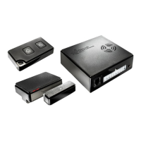
The Thitronik WiPro III + safe.lock is an advanced alarm system designed for Fiat Ducato X250 Euro 4 models (2006-2011), offering enhanced security features for recreational vehicles. This system integrates seamlessly with the vehicle's existing CAN bus and central locking system, providing comprehensive protection against unauthorized access.

Function Description

The WiPro III + safe.lock system operates by monitoring various access points of the vehicle, including doors, windows, and hatches, using wireless magnetic contacts. When the system is armed, any unauthorized opening of these monitored points triggers an alarm. The system also includes a safe.lock function that controls the central locking system, providing an additional layer of security.

Key functionalities include:

  • Wireless Magnetic Contacts: The system utilizes 868 MHz wireless magnetic contacts to secure windows, doors, and hatches. These contacts consist of a transmitter housing and a magnet. When the magnet moves away from the transmitter, indicating an opening, a signal is sent to the central unit.
  • CAN Bus Integration: The WiPro III + safe.lock connects to the vehicle's CAN bus, allowing it to communicate with the on-board computer and leverage existing vehicle systems for alarm activation and status monitoring. This integration ensures that the alarm system functions in harmony with the vehicle's electronics.
  • Central Locking Control (safe.lock): The safe.lock feature enables the alarm system to control the vehicle's central locking. This means that arming the alarm system can also lock the doors, and disarming it can unlock them. It also provides specific control for front and rear doors.
  • Alarm Triggering: In the event of an intrusion, the system triggers both acoustic and visual alarms. The acoustic alarm sounds for approximately 30 seconds, while the visual alarm (flashing warning lights) lasts for about 180 seconds.
  • Status LED: A dedicated status LED provides visual feedback on the system's operational status, such as armed/disarmed state, and during teach-in procedures.
  • Teach-in Functionality: The system allows for easy "teach-in" of wireless magnetic contacts and other transmitters (like gas alarms or radio cable loops). This process involves activating each contact multiple times until successful storage is acknowledged by a beep and the LED.
  • Diagnostics Mode: A diagnostics mode can be activated to check for CAN bus activity, indicated by the flickering of a green LED. This helps in troubleshooting connection issues.
  • Arming Signals: If a series of short beeps is emitted during arming, it indicates that one of the taught-in magnetic contacts is open. Despite this, the system will still arm.
  • Ignition Deactivation: The system is designed to deactivate automatically when the ignition is active, preventing accidental alarms while the vehicle is in use.

Important Technical Specifications

  • Vehicle Compatibility: Fiat Ducato X250, Euro 4 (2006-2011).
  • Wireless Frequency: 868 MHz for magnetic contacts.
  • Power Supply: Protected via fuse 39 with 10 A.
  • CAN Bus Interface: Configurable via an 8-way DIP switch on the circuit board (switches 2 and 6 set to 'on' for Ducato).
  • Status LED: Requires an 8mm drilled hole for installation.
  • Central Locking Control Pins: Pin 28 (blue/yellow) for front doors, Pin 50 (pink/violet) for rear doors.
  • CAN Low/High Connections: Typically from Green insert (pin 5 pink/white for CAN low, pin 6 pink/black for CAN high) or Black insert (pin 25 pink/white for CAN low, pin 24 pink/black for CAN high). Note that starting in model year 2010, pink/black may be replaced by violet/black.
  • Horn Actuation: Connects to brown/green wire (pin 8) on the steering column (may be green/brown in later models).
  • Ignition Connection: Connects to white/black wire of the green plug on the on-board computer.

Usage Features

  • Remote Control Integration: The system is armed and disarmed using the vehicle's original remote control. After installation, it may require several lock/unlock cycles for the CAN bus data to synchronize.
  • User Feedback: Acknowledgment of activation is provided through a beep and flashing direction indicators. The status LED also flashes when armed.
  • Door Open Warning: If a driver's cab door is open, the vehicle will not lock, and the system will not activate, preventing false alarms and ensuring proper security.
  • Manual Alarm Triggering: The alarm can be triggered by mechanically opening the driver's side door from the inside with the door handle or from the outside by unlocking with the mechanical key and opening the door.
  • Alarm Interruption: The alarm can be interrupted by pressing the 'unlock' button on the remote control.
  • Flexible Mounting Options for Magnetic Contacts: Magnetic contacts can be mounted in various orientations (lying left, lying right, upright, windowpane) to accommodate different vehicle designs and space constraints. Mounting adaptors (art. no. 100428, 100729) are recommended for bridging larger distances or optimal antenna alignment.

Maintenance Features

  • Professional Installation: The manual emphasizes that installation should only be carried out by professional service companies with appropriate background knowledge of vehicle electrics and electronics. This ensures correct functioning and prevents damage or injury.
  • Troubleshooting Guide: The manual includes a comprehensive troubleshooting section for common issues:
    • System not responding to wireless key commands but beeping on power supply: Solutions include checking CAN connection, using diagnostics mode to verify CAN bus activity, and ensuring correct connection execution.
    • System not responding to wireless key commands and no beep on power supply: Solutions involve checking power supply, verifying correct pin occupation on the front connector, ensuring correct crimp connection, checking ignition status (system is deactivated when ignition is active), and inspecting fuse F39.
    • Open contact signaled during arming despite all contacts being closed: Solutions include checking the distance between the transmitter and magnet, opening and closing all contacts multiple times, and if the issue persists, temporarily disconnecting and reconnecting the power supply or removing fuse F39.
  • Adhesive Pad Mounting Guidelines: For mounting wireless magnetic contacts with adhesive pads, surfaces must be clean, dry, and grease-free. Pretreatment with a cleaning agent is recommended. Installation should not occur below 15 °C, and adhesive pads reach full strength after approximately 24 hours.
  • Screw Fixing Option: If adhesive mounting is not feasible, screw fixing is also possible, with markings provided inside the transmitter housing.
  • Circuit Board Alignment: Crucially, the circuit board within the transmitter housing must not be aligned with the transmitter LED pointing towards the magnet. Incorrect alignment can lead to successful teach-in but prevent alarm activation. The magnet should always move between the yellow and blue areas relative to the reed switch for proper operation.
  • Regular Checks: The function test outlined in Step 9 serves as a crucial post-installation check to ensure all components are working as intended.

Thitronik WiPro III + safe.lock Specifications

General IconGeneral
BrandThitronik
ModelWiPro III + safe.lock
CategoryCar Alarm
LanguageEnglish

Related product manuals