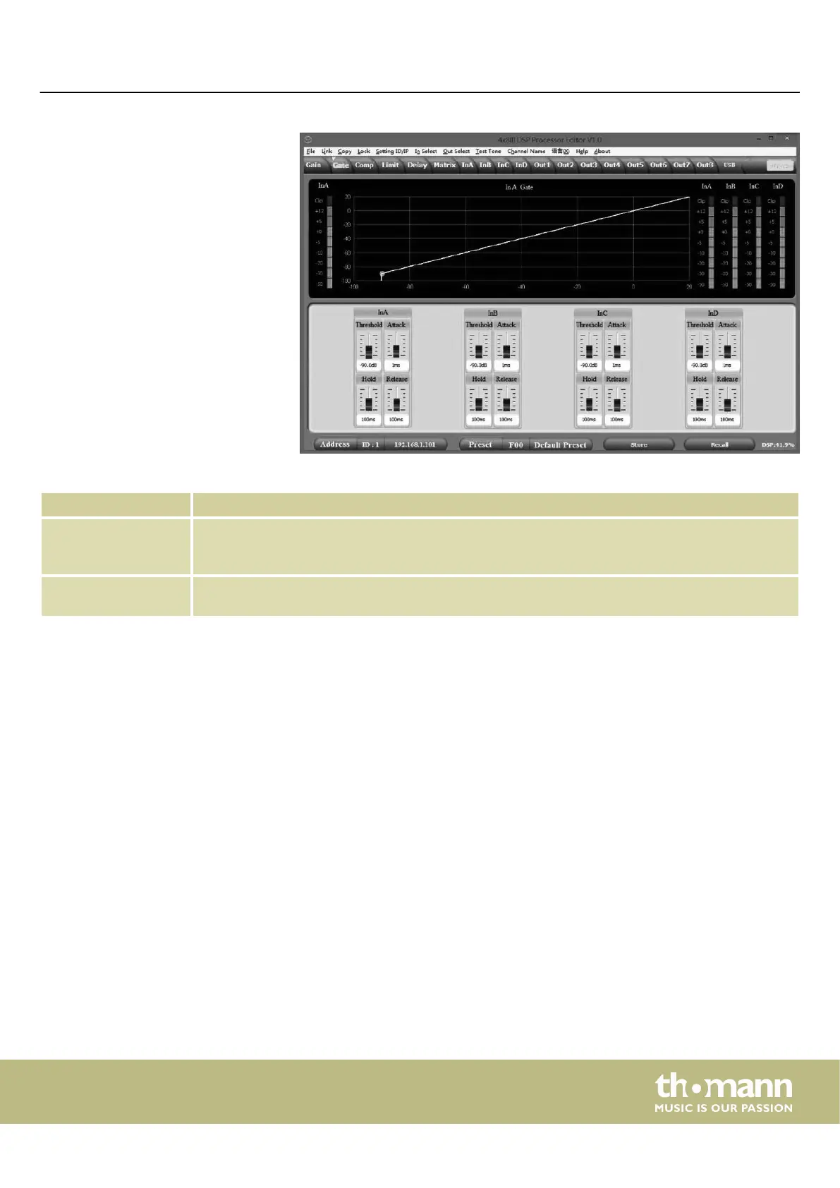
Range Meaning
Display area Shows the current settings of the noise gate for the respective channel, with a symbolic level indi‐
cator symbol appearing next to it for the input channels. The red dot in the curve corresponds to the
current signal.
Control area Drag the faders with the mouse to set the noise gate parameters for all input and output channels:
Threshold, hold, attack, release.
‘Gate’ tab
Operating on the computer
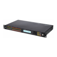
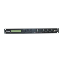
FIR DSP 408
21
 Loading...