Range Meaning
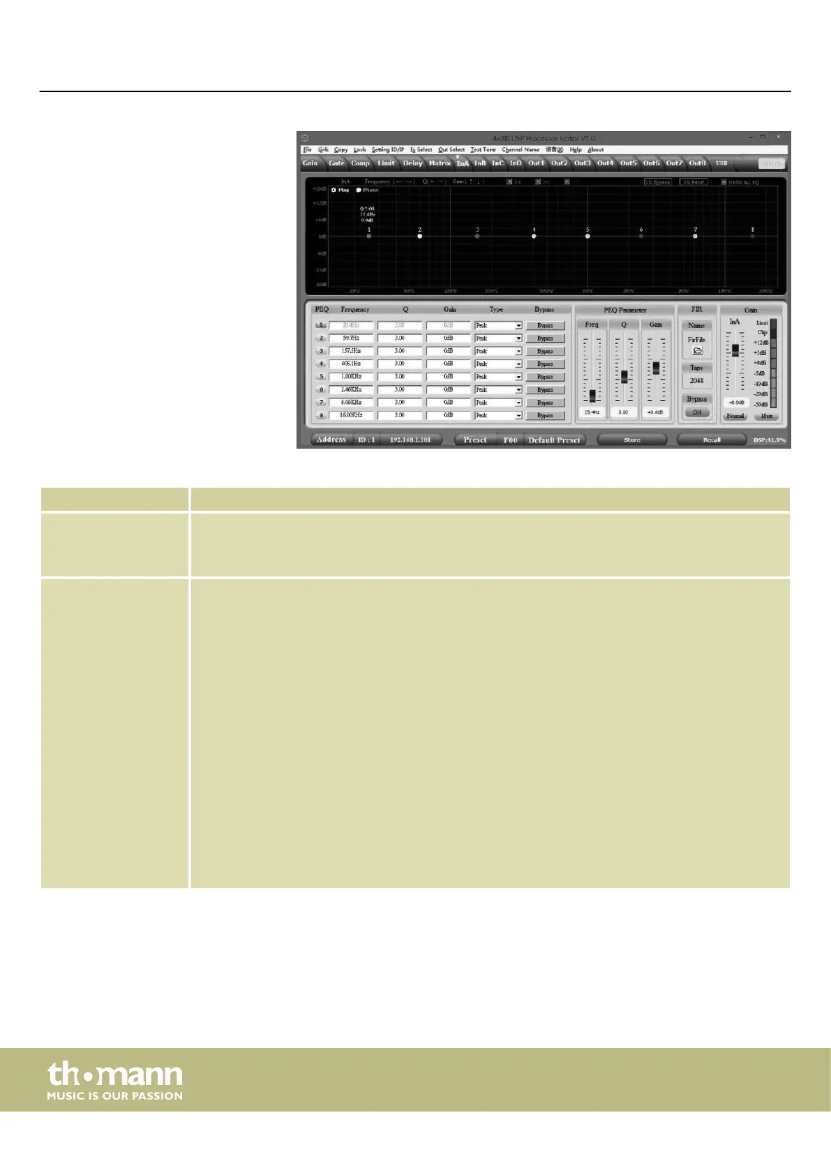
Display area Use the radio buttons ‘Mag’ or ‘Phase’ to switch the diagram from Cartesian coordinates (level vs.
frequency) to polar coordinates (angle vs. frequency).
Use the radio button ‘SHOW ALL EQ’ to display the parameters for all nine frequency bands.
Control area For each input channel and all nine frequency bands (numbered with ‘PEQ’ ) you can enter the param‐
eters of the parametric equalizer directly as numerical values in the left part of the window: Centre
frequency, lter quality, slope, lter type. With the ‘Bypass’ button, the equalizer for the respective
frequency band and the respective channel can be bypassed temporarily.
In the middle part of the window ( ‘PEQ Parameter’ ) you can adjust the parameters centre frequency,
lter quality and slew rate with the faders or the arrow keys on the PC keyboard. The setting refers to
the frequency band that is highlighted green in the left part of the window.
The input channel can support 2048 FIR taps. To this, load the data in the folder ‘Firle’ (supported le
formats: csv and txt). After import, the FIR coecients are displayed, the ‘PEQ’ diagram shows the
‘FIR’ curve. Use the ‘Bypass’ button to temporarily bypass the lter. Note: Since the FIR data is so
extensive, only all channels together can support 4096 FIR taps. Each channel requires a homoge‐
neous distribution of FIR resources and the PC software displays the size of the FIR resources in the
lower right corner. Once exhausted, the PC software displays a warning message. Better use only
512 FIR taps. If you use more taps, the process time on the PC becomes considerably longer and leads
to longer delays; when using 1024 taps, the delay is already more than 10 ms.
Drag the fader in the right part of the window using the mouse to set the level for the input channel.
The ‘Mute’ button mutes or unmutes the respective channel. The ‘Normal’ / ‘Inverse’ button inverts
the phase of the respective channel by 180° when needed.
‘In’ tab
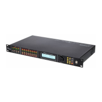
Operating on the computer
digital speaker management system
26
 Loading...