EasyManua.ls Logo

Thomas & Betts TBM5 - User Manual

Thomas & Betts TBM5
6 pages
Print Icon
To Next Page IconTo Next Page
Loading...
TA00084 G Page 1 of 6
Read and understand all of the instructions
and safety information in this manual before
operating or servicing this tool.
TBM5, TBM5-S and TBM5-SV
Compression Tool Instructions
1.0 Operating Instructions . . . . . . . . . . . . . . . . . . . 2
1.1 Tool Description . . . . . . . . . . . . . . . . . . . . . . 2
1.2 Applications . . . . . . . . . . . . . . . . . . . . . . . . 2
1.3 Choosing the Die Nest . . . . . . . . . . . . . . . . . . . 2
1.4 Removing and Installing Die . . . . . . . . . . . . . . . . . 2
1.5 Preparing the Conductor . . . . . . . . . . . . . . . . . . 3
1.6 Making a Compression . . . . . . . . . . . . . . . . . . . 3
2.0 Installation Test Procedure . . . . . . . . . . . . . . . . . 4
2.1 Installation Test Procedure . . . . . . . . . . . . . . . . . . 4
2.2 Tensile Test Procedure . . . . . . . . . . . . . . . . . . . 4
3.0 Calibration Verification . . . . . . . . . . . . . . . . . . . 5
3.1 Visual Inspection . . . . . . . . . . . . . . . . . . . . . . 5
3.2 Handle Spread Check . . . . . . . . . . . . . . . . . . . . 5
3.3 Gaging Procedure . . . . . . . . . . . . . . . . . . . . . 5
3.4 Gaging Table . . . . . . . . . . . . . . . . . . . . . . . 6
Table of Contents
Question and Answer IconNeed help?

Do you have a question about the Thomas & Betts TBM5 and is the answer not in the manual?

Summary

Operating Instructions

Tool Description

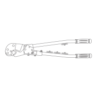
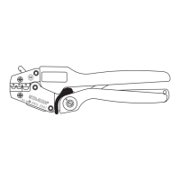
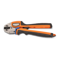
Details the components of the compression tool, including the tool head, ram, and handles.

Applications

Outlines the types of lugs, splices, and C-taps suitable for use with the tool.

Choosing the Die Nest

Guides users on selecting the correct die nest based on connector color coding.

Removing & Installing Die

Provides instructions for safely removing and installing dies into the tool head.

Preparing the Conductor

Explains proper conductor stripping and preparation for aluminum conductors.

Making a Compression

Details the process of making a proper compression on conductors using the tool.

Installation Test Procedure

Installation Test Procedure

Describes the procedure for testing tool calibration using a minimum of six terminals per die nest.

Tensile Test Procedure

Details the method for performing tensile pull-out tests on installed terminals.

Calibration Verification

Visual Inspection

Instructs on visually inspecting the tool for defects that could affect performance.

Handle Spread Check

Explains how to check and adjust handle spread for proper tool adjustment and reliable compression.

Gaging Procedure

Outlines the procedure for using a gage pin to verify die nest dimensions.

Gaging Table

Provides a table with minimum-maximum gaging limits for different die colors and catalog numbers.

Thomas & Betts TBM5 Specifications

General IconGeneral
TypeCrimp Tool
ModelTBM5
MaterialSteel
Die SetIncluded
Crimping Capacity (AWG)10
ApplicationElectrical crimping

Related product manuals