EasyManua.ls Logo

Thomas&Betts TBM8 - User Manual

Thomas&Betts TBM8
6 pages
Print Icon
To Next Page IconTo Next Page
Loading...
TA01978 C Page 1 of 6
Read and understand all of the instructions
and safety information in this manual before
operating or servicing this tool.
TBM8 and TBM8S
Compression Tool Instructions
1.0 Operating Instructions . . . . . . . . . . . . . . . . . . . 2
1.1 Tool Description . . . . . . . . . . . . . . . . . . . . . . 2
1.2 Applications . . . . . . . . . . . . . . . . . . . . . . . . 2
1.3 Choosing the Die Nest . . . . . . . . . . . . . . . . . . . 2
1.4 Removing and Installing Die . . . . . . . . . . . . . . . . . 2
1.5 Preparing the Conductor . . . . . . . . . . . . . . . . . . 3
1.6 Making a Compression . . . . . . . . . . . . . . . . . . . 3
2.0 Installation Test Procedure . . . . . . . . . . . . . . . . . 4
2.1 Installation Test Procedure . . . . . . . . . . . . . . . . . . 4
2.2 Tensile Test Procedure . . . . . . . . . . . . . . . . . . . 4
3.0 Calibration Verifi cation . . . . . . . . . . . . . . . . . . . 5
3.1 Visual Inspection . . . . . . . . . . . . . . . . . . . . . . 5
3.2 Handle Spread Check . . . . . . . . . . . . . . . . . . . . 5
3.3 Gaging Procedure . . . . . . . . . . . . . . . . . . . . . 5
3.4 Gaging Table . . . . . . . . . . . . . . . . . . . . . . . 6
Table of Contents
Question and Answer IconNeed help?

Do you have a question about the Thomas&Betts TBM8 and is the answer not in the manual?

Overview

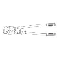
The Thomas & Betts TBM8 and TBM8S are compression tools designed for installing Color-Keyed® lugs and splices, C-Taps, and other connectors on various conductor types. These tools are primarily used for making reliable electrical connections through compression.

Function Description:

The TBM8 and TBM8S tools perform mechanical compression to create secure electrical connections. The core function involves placing a connector and conductor within a die nest and then applying force by closing the tool handles, which compresses the connector onto the conductor. The TBM8S model is equipped with a unique Shure Stake® full stroke compelling mechanism, ensuring that the compression cycle is completed fully for optimal connection integrity. This mechanism prevents partial compressions, which could lead to unreliable connections. If a release is necessary before the full cycle is complete, the Shure Stake® mechanism can be disengaged by slightly squeezing the handles and pushing the dowel pin.

Important Technical Specifications:

  • Conductor Compatibility:
    • Copper: #8 to 500 MCM
    • Aluminum: #10 to 350 MCM
  • Connector Compatibility:
    • Color-Keyed® lugs and splices
    • C-Taps (catalog numbers 54705 to 54750)
    • UL and/or CSA monogrammed connectors marked AL (for aluminum conductors only) or AL9CU (for aluminum and copper conductors). It is crucial to use only listed Thomas & Betts connectors with this tool to ensure compliance with established standards.
  • Die Nests: The tools utilize interchangeable die nests, which are color-coded to match the corresponding connectors. The die nests have specific groove colors (e.g., Red, Blue, Grey, Green, Pink, Black, Orange, Purple, Yellow, Gold, Tan, Olive, Ruby, White, Brown) and equivalent hex die code numbers (e.g., 21, 24, 29, 33, 37, 42, 45, 50, 54, 62, 60, 66, 71, 76, 87).
  • Gaging Specifications (for Calibration Verification):
    • Each die nest has a specific minimum and maximum gaging range (e.g., .165-.181 for Red 13461, .855-.883 for Brown 13468).
  • Handle Spread (for Calibration Verification): In a properly adjusted tool, the distance between the handle grips should be between 11" and 14" when the ram is touching the die and the tool is laid flat.

Usage Features:

  • Die Selection: Users must match the color on the connector to the color on the die nest. A chart is provided to guide this selection. Some die nests may have multiple color bands, indicating compatibility with multiple Color-Keyed® connectors.
  • Die Installation and Removal: Dies are easily removed by loosening the die locking screw and pulling the die out when the handles are fully extended. Installation involves holding the die with the desired crimping nest and color code facing the lower right corner, then tightening the die locking screw.
  • Conductor Preparation:
    • Insulation must be stripped without cutting or nicking conductor strands, following the strip length specified in the connector's instruction sheet.
    • For aluminum conductors, a thin layer of joint compound should be smeared onto the cable and brushed in with a wire brush or emery cloth.
  • Compression Procedure:
    1. Insert the prepared conductor into the connector.
    2. Position the connector in the die grooves so that the die is between the color code marks for copper and on the color code marks for aluminum.
    3. For connectors requiring multiple compressions, the first compression should be made nearest the terminal's tongue or the splice's center, then progressively working toward the barrel's end.
    4. Close the tool handles completely for each compression until the Shure Stake® mechanism releases (for TBM8S).
  • Safety: Users are warned to keep fingers clear of die nests when handles are brought together. The Shure Stake® safety release on the TBM8S allows for disengagement of the ratchet mechanism if needed before a full crimp cycle is complete.

Maintenance Features:

  • Calibration Verification: Calibration verification should be performed whenever damage is suspected or as operating conditions warrant. This involves:
    • Visual Inspection: The tool must be free of cracks, sharp edges, burrs, dents, or scratches that could affect performance.
    • Handle Spread Check: This verifies proper tool adjustment. The distance between the handle grips is measured when the tool is laid flat with the ram touching the die. If the spread is outside the 11" to 14" range, the adjusting screw (located near the ram) can be turned clockwise to increase the distance or counter-clockwise to decrease it, after loosening the lockscrew. The lockscrew must be tightened after adjustment.
    • Gaging Procedure: This involves inserting a gage pin into the die nest with minimal hand pressure while the handles are fully closed. The gage pin's measurement must fall within the specified minimum and maximum limits for the particular die nest, as outlined in the gaging table. Dies should be wiped clean before gaging.
  • Tensile Test Procedure (for TBM8S only): This procedure is used to verify the quality of the compression.
    1. Install a test sample (connector and conductor) in a tension-testing machine or pull-test fixture.
    2. Apply a gradual axial pull until the connection fails.
    3. The pull force required to separate the terminal from the wire must meet or exceed the minimum pullout values specified in a table (e.g., 70 lbs for #12 copper, 400 lbs for #500 copper). For C-taps and wire joints, only the smallest wire in the combination is tested for pullout.
  • Warranty and Service: Thomas & Betts provides a warranty against defects in materials and workmanship. Misuse or unauthorized modification voids warranties. For parts or service, users can contact the Thomas & Betts Tool Service Center.

Thomas&Betts TBM8 Specifications

General IconGeneral
BrandThomas&Betts
ModelTBM8
CategoryTools
LanguageEnglish