1.5
1.6
ALUMA
SHIELD
CABLE
DIE
DIE
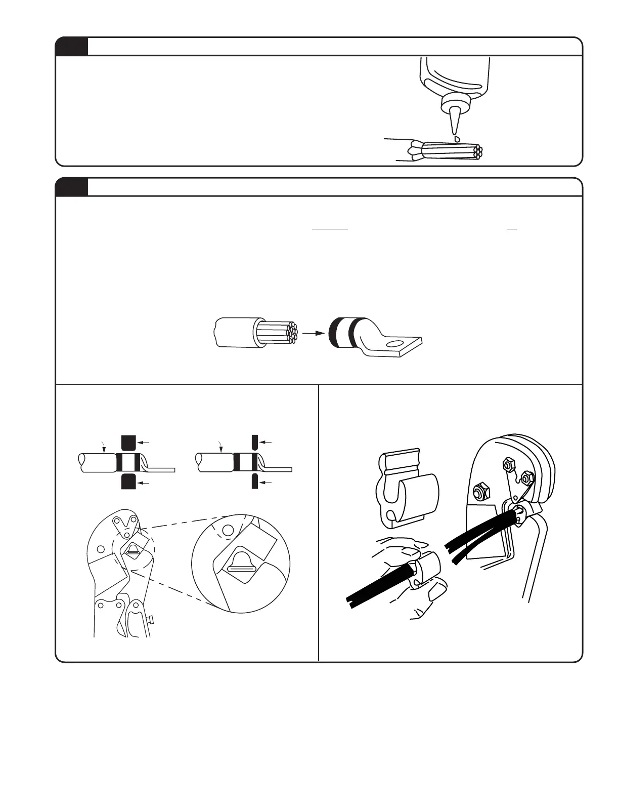
1. Insert prepared conductor into connector.
2. Locate connector in die grooves of tool, so the die is between the color code marks for copper and on the color
code marks for aluminium, see graphics below.
3. Some connectors require more than one compression. Refer to the instruction sheet supplied with the connectors
regarding the number of compressions required. If more than one compression is indicated, the fi rst compression
should be in the indicated area nearest to the tongue of a terminal and nearest the center of a splice, and then
working progressively toward the end of the barrel.
4. Close handles of tool completely for each compression.
STEP 1
CABLE
DIE
DIE
TYPICAL COPPER
INSTALLATION
STEP 2 STEP 3
TYPICAL ALUMINUM
INSTALLATION
TA01978 C Page 3 of 6
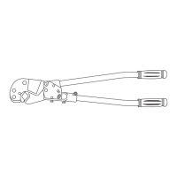
1. Strip insulation properly without cutting or nicking
the conductor strands. Refer to the instruction sheet
supplied with the connectors regarding strip length.
2. For aluminum conductor, smear a thin layer of joint
compound onto the cable and brush it in with a wire
brush or emery cloth.
MAKING A COMPRESSION
PREPARING THE CONDUCTOR