3.0
3.1
VISUAL INSPECTION
3.3
GAGING PROCEDURE
CALIBRATION VERIFICATION
3.2
HANDLE SPREAD CHECK
RAM JUST
TOUCHING DIE
ADJUSTING SCREW
MEASURE
HERE
HANDLE
A
RETAINING SCREW
LOCK SCREW
FLAT SURFACE OR
TABLE TOP
DIE
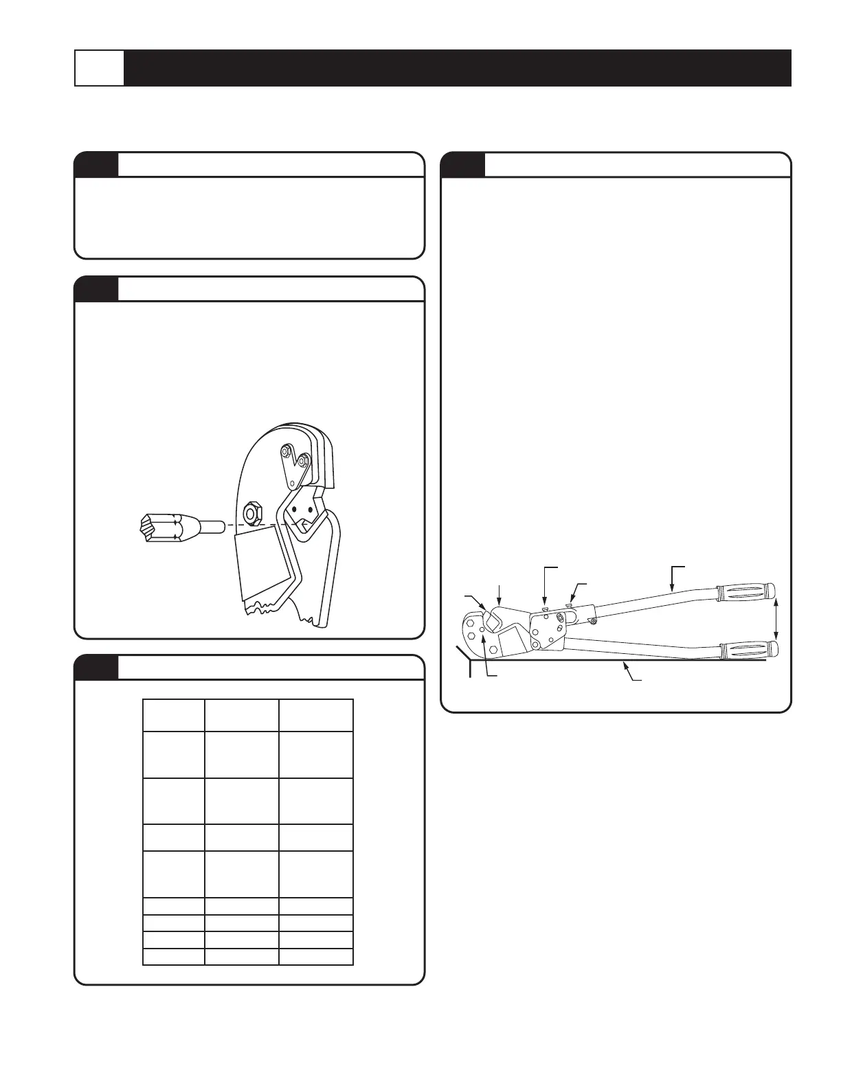
To ensure the tool will produce a reliable
compression, the tool must be properly adjusted.
CHECKING TOOL ADJUSTMENT
1. Insert die in place.
2. Lay tool on a fl at surface. Open handle A and
allow it to close under its own weight. The ram
should be touching the die.
3. Measure distance between handle grips. In
a properly adjusted tool, the distance should
be between 11” and 14”. If it is less than 11”
or more than 14”, the tool needs adjustment.
(See graphic below).
ADJUSTING TOOL
1. Loosen lockscrew.
2. To increase distance between handles, turn
adjusting screw clockwise.
3. To decrease distance between handles, turn
adjusting screw counterclockwise.
4. Tighten lock screw.
5. Recheck handle distance. Adjust again, if
necessary.
NOTE: Calibration verifi cation of the tool should be performed whenever damage or suspected damage has occurred or as
often as operating conditions warrant.
TA01978 C Page 5 of 6
1. Tool must be free of cracks, sharp edges and
other obvious imperfections that may affect
performance of the tool. Nest area must be free
of burrs, dents or scratches.
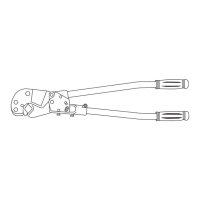
NOTE: Wipe dies before gaging.
1. Squeeze handles until jaws are fully closed.
2. Select gage pin which can be inserted into nest
with minimal hand pressure. See graphic below.
3. Gage pin should fall between the limits shown on
tables in section 3.4.
GAGE PIN
GROOVE
COLOR
DIE
CAT. NO.
GAGING
MIN. - MAX.
RED
BLUE
GRAY
BROWN
13461
.165-.181
.181-.210
.230-.251
.260-.281
GREEN
PINK
BLACK
ORANGE
13462
.313-.335
.351-.371
.383-.406
.429-.454
PURPLE
YELLOW
13463
.480-.503
.529-.562
GOLD
TAN
OLIVE
RUBY
13464
.383-.406
.429-.454
.480-.503
.533-.553
WHITE 13465 .609-.632
RED 13466 .653-.677
BLUE 13467 .686-.710
BROWN 13468 .855-.883
3.4
GAGING TABLE