EasyManua.ls Logo

THORLABS ELL14 - User Manual

THORLABS ELL14
22 pages
Print Icon
To Next Page IconTo Next Page
Loading...
ELL14 Motorized SM1 Optic Rotator
ELL14 and ELL14K
Motorized SM1 Optics
Rotator Kit
Operating Manual
Original Instructions
Question and Answer IconNeed help?

Do you have a question about the THORLABS ELL14 and is the answer not in the manual?

Summary

Chapter 1 Introduction

Environmental Conditions

Specifies operating environment limits including location, altitude, temperature, and humidity.

Mounting

Details how to mount the rotator, including cage systems and post mounting options.

Chapter 2 Safety

General Warnings and Cautions

Provides essential safety warnings regarding electrical shock, user injury, and product damage.

Chapter 3 Description

Environmental Conditions

Specifies operating environment limits including location, altitude, temperature, and humidity.

Mounting

Details how to mount the rotator, including cage systems and post mounting options.

Chapter 4 Operation

Getting Started

Steps for initial setup, including installation, PC connection, and homing the stage.

Homing Procedure

Explains the process of homing the rotator using optical and magnetic sensors for positioning.

Position Error Compensation

Describes the algorithm that corrects positioning errors for improved accuracy.

Controlling the Rotator

Overview of methods to control the rotator, including handset, software, and digital lines.

Hand-held Controller

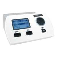
Details how to use the physical handset for manual control of the rotator.

Software Control

How to use the Elliptec software for remote control and configuration of the rotator.

Communications Protocol

Details the communication protocol for custom applications and multi-drop bus.

Connecting Multiple Devices

Instructions for connecting and addressing multiple rotator units on a single bus.

Controlling Without Handset

How to control the rotator using digital lines on Connector J1.

Connector J1 Pin Out

Details the pin assignments and functions for Connector J1.

Frequency Search

How to perform a frequency search to optimize motor performance.

Periodic Cycling

Recommends periodic movement over full travel to maintain performance.

Restoring Factory Settings

Procedure to reset the rotator to its default factory settings.

Simultaneous Movement

How to synchronize movements of multiple connected devices.

Chapter 5 Troubleshooting and FAQ

Frequently Asked Questions

Common issues and their solutions, such as rotator not moving or homing.

Device Not Responding

Explains why the device may not respond during cleaning/optimization and handling tips.

Typical Product Life Time

Information on the expected lifespan and factors affecting it.

Making a Picoflex Cable

Step-by-step guide to creating a cable for daisy chaining devices.

Chapter 6 Specifications

General Specifications

Lists key performance characteristics like travel, speed, accuracy, and dimensions.

Chapter 7 Regulatory

Declarations of Conformity (Europe)

EU compliance statements for Machinery, EMC, and RoHS directives.

Declarations of Conformity (USA)

FCC compliance statement for Class A digital devices.

Chapter 8 Thorlabs Worldwide Contacts

Contact Information

Provides contact details for sales and technical support across different regions.

Overview

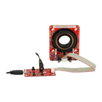
The ELL14 and ELL14K are motorized SM1 optics rotators designed for OEM applications, featuring a resonant piezo motor circuit and bare modules. These rotators are capable of adapting to 30 mm and 60 mm cage systems and can also be post-mounted. The resonant piezo design provides fast response times and precise positioning, making them particularly suitable for scanning applications.

Function Description

The ELL14 rotator features a central SM1-threaded aperture for optics and offers a travel range of 720° rotation. The angular position is displayed from 0 to 359.99°. If the rotator moves beyond 359.99°, the display resets to zero and counts up again. The unit is designed for closed-loop applications, providing rotational positioning with a resolution of 44.0 µrad.

Homing is achieved through a two-stage process: a reflecting optical sensor (IR) provides coarse positioning (0.5 to 1.0 mm), followed by a magnetic sensor for fine positioning (1.0 µm resolution). The magnetic sensor is also used for subsequent moves. The ELL14K evaluation kit includes a hand-held controller for manual jogging and positioning, and the unit can also be controlled remotely via PC-based software available from Thorlabs. A compatible USB driver and source code are part of the software download package.

The high-speed digital signal processing (DSP) architecture supports a multi-drop serial communication protocol. Digital I/O lines allow manual control of movement and state by switching lines high (5V) or low (0V). The rotator includes a positioning error compensation algorithm that automatically calculates and applies an error compensation value for subsequent movements, typically optimizing within 2 to 6 motions.

Usage Features

The ELL14 module requires an external 5V power supply, with a suitable PSU included in the kit. For third-party PSUs, the interface board uses a DC Jack connector (6.3mm OD (GND), 2.1mm ID (+5V)).

The rotator can be controlled in three ways:

  • Hand-held Controller: The ELL14K evaluation kit includes a hand-held controller with two buttons (FW for forward, BW for backward) for controlling the rotator's position. It also provides connections for a host PC and the external 5V power supply, allowing operation without a PC. An LED (green) indicates power, and another LED (red) indicates when the device is in motion. To jog forward, press and hold JOG, then press FW. To jog backward, press and hold JOG, then press BW. The default jog step is 45 degrees and can be adjusted via software. Homing is performed by pressing the BW button.
  • Software Control: When connected to a host PC, the rotator can be controlled remotely using the Elliptec software, downloadable from Thorlabs. After connecting the hand-held controller to the rotator, 5V power supply, and PC USB port, the software allows selection of the COM port, device enumeration, and control. The software GUI enables setting home offset, homing the rotator, and performing jog moves.
  • Custom Applications: Users can write custom applications using the messages described in the communications protocol document. Homing and jogging functionalities are also accessible by applying voltages to the digital lines on Connector J1.

In all control modes, the angular position is displayed from 0 to 359.99°. The unit will not respond to requests for moves beyond 359.99°, generating an error message.

For multiple devices, the multi-drop serial communication protocol allows individual control via Elliptec software or third-party applications by assigning unique addresses to each device. Synchronized movement of multiple devices is possible using the handset or software.

Maintenance Features

  • Frequency Search: Due to load, build tolerances, and mechanical variances, the default resonating frequency may not provide optimal performance. A frequency search can be performed via the Main GUI Settings panel in the ELLO software or using the serial communication line (SEARCHFREQ_MOTORX message) to optimize operating frequencies for backward and forward movement. This search can also be performed manually by restoring factory settings.
  • Periodic Cycling: Devices should be periodically moved over their full range of travel to minimize debris buildup on the track and prevent the motors from digging grooves in frequently used areas. A travel cycle is recommended every 10,000 operations.
  • Restoring Factory Settings: Factory settings can be restored during the startup (calibration) test. This involves removing power, disconnecting the USB cable, pressing and holding the BW button, powering up and reconnecting the USB, waiting for the red LED to switch on, and then releasing BW. The unit will reboot and load default factory values.
  • Cleaning and Handling: The rotator and interface board are robust. To ensure reliable operation, the plastic track contacted by the motors should be kept free of oils, dirt, and dust. While gloves are not necessary, touching the track should be avoided to prevent oil transfer from fingerprints. If cleaning is required, isopropyl alcohol or mineral spirits (white spirit) can be used. Acetone should not be used as it will damage the plastic track.
  • Optimization: The cleaning and optimization routines block device communication for several minutes. During these routines, the unit's temperature may increase, so consecutive cleaning and optimization routines should be avoided. A 20-minute cool-down period is recommended after optimization or cleaning. If optimization fails, the device will attempt to reload previous settings; if this also fails, a frequency search should be performed.
  • Environmental Conditions: The unit is designed for indoor use only, at altitudes up to 2000 m, temperatures between 15°C and 40°C, and humidity below 80% RH (non-condensing) at 31°C. It should not be exposed to corrosive agents, excessive moisture, heat, dust, or magnetic fields. If stored at low temperatures or high humidity, it must reach ambient conditions before powering up. The unit is not designed for continuous operation; a duty cycle of less than 40% is recommended, and never exceeding 60% for more than a few seconds.
  • Safety: When connecting to a PC, ensure the PC is switched ON before connecting the stage to the USB port to prevent damage. The equipment is susceptible to electrostatic discharge, so anti-static precautions must be taken. Spillage of fluids should be avoided and cleaned immediately. The motor housing may become hot during prolonged operation, but this does not affect motor function. The PCB should not be bent, and motor wires should not be bent over the motor spring or allowed to contact other moving parts. The ribbon cable connector is plastic and not robust, so force should not be used when connecting, and unnecessary plugging/unplugging should be avoided.

THORLABS ELL14 Specifications

General IconGeneral
MaterialAluminum
InterfaceUSB
Load Capacity5 N
Power Supply5 VDC
Operating Temperature Range0°C to 40°C

Related product manuals