Rev 19 Oct 2020
Page 15
Chapter 3 Installation & Initial Set Up
6) Note the serial numbers then connect the galvo motors to their associated driver
boards
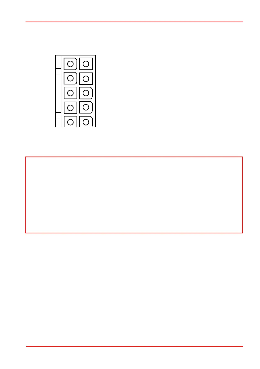
Fig. 3.10 Galvo Assembly Motor Connector Pin Identification
7) Connect a command input (e.g. function generator) to J7 of each driver board as
shown in Fig. 3.11. J7 accepts Molex pins Pt No 56134-9100.
Note
The scanner accepts a differential analog command input. If the scaling is 0.8 Volt
per degree mechanical movement (see Section 3.3.5.), -10 V to +10 V gives -12.5
to +12.5 degrees mechanical movement. The driver will attempt to set the mirror
position to the command input value.
Pin 3 (DRV_OK) is an open collector output that is low when the board is operating
normally and floating if a fault occurs. To use Pin 3 as a fault indicator, connect a
pull-up resistor to give a high signal when the fault occurs. DRV_OK limits are 30 mA
30 V.
Do not connect a relay to this output.
Pin 1 Motor + Coil (power shield floating)
Pin 2 Motor -Coil (power shield floating)
Pin 3 Not Used
Pin 4 Not Used
Pin 5 Position Sensor B Current
Pin 6 Position Sensor Ground
Pin 7 Position Sensor A Current
Pin 8 Position Sensor Power
(Automated Gain Control)
Pin 9 Position Sensor Cable Shield
Pin 10 Not Used