Rev 19 Oct 2020
Page 19
Chapter 4 Operation
4.4 Recommended Scanning Angles
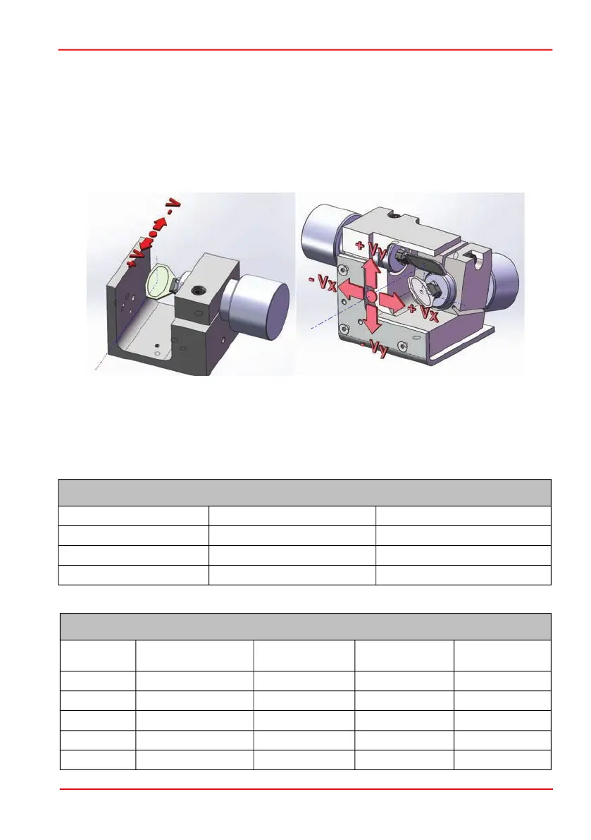
Although the maximum mechanical scan angle is stated as ±20° in Section 3.2.5. the
maximum angle achievable without interference
is dependent upon a number of
conditions. Firstly, the larger the diameter of the input laser beam, the smaller the
achievable scanning angle. Secondly, the applied input voltage causes the laser
beam to move away from the center of the mirrors. The larger the input voltage then
the greater the movement from the center, as shown below.
Lastly, on dual-axis systems, there is an offset alignment between the X and Y axis
mirrors that also limits the scan angle.
The table below gives recommended scanning angles for various beam diameters.
GVS011, GVS111, GVS211, GVS311 and GVS411
Input Beam Diameter Mechanical Scan Angle Optical Scan Angle
7 mm and less ± 20° ± 40°
8 mm + 20°, -16° + 40°, -32°
10 mm + 20°, -8° + 40°, -16°
GVS012, GVS112, GVS212, GVS312 and GVS412
Input Beam
Diameter
Mechanical
Scan Angle X
Optical
Scan Angle X
Mechanical
Scan Angle Y
Optical
Scan Angle Y
2 mm ± 15.5° ±31° ± 20° ± 40°
4 mm ± 13.5° ±27° ± 20° ± 40°
6 mm ± 11.5° ±23° + 20°, - 17.5° + 40°, - 35°
8 mm ± 10° ± 20° ± 15° ± 30°
10 mm ± 8.5° ± 17° + 5°, -13° + 10°, -26°
Input Axis
Output Axis
Input Axis
Output
Axis
 Loading...