Page 14 20381-D02
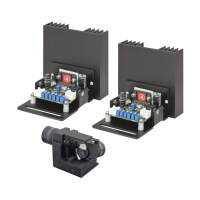
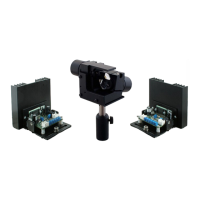
Single- and Dual-Axis Scanning Galvo Systems for Large Beam Diameters
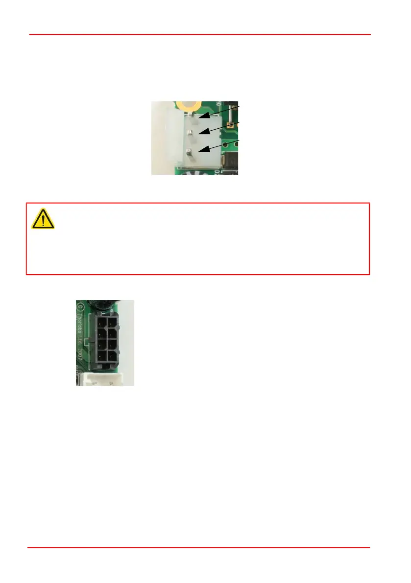
4) Identify connector J10 on each driver board, and make power connections as
shown below. Thorlabs supply a suitable PSU (GPS011) for powering a single or
dual axis system (see Section 3.2.1.). A bare cable, crimp connectors (Molex Pt
No 2478) and housings for use with general lab PSUs is supplied with each driver
board.
Fig. 3.8 J10 Power Connector Pin Identification
5) Connect a motor cable to the connector J9 on each driver board as shown below.
Fig. 3.9 J9 Motor Connector Pin Identification
Caution
During items (5) and (6) use only the cables supplied. Do not extend the cables.
The driver boards and motors are calibrated with these cables. Using different
cables will affect the performance of the system. Longer cables are available as
a custom part but the units will require re-calibration if these are not specified
at time of order. Contact tech support for more details.
1 +15V
2 Ground
3 -15V
1
2
3
4
5
6
7
8
Pin 1 Position Sensor A Current
Pin 2 Position Sensor Ground
Pin 3 Position Sensor Cable Shield
Pin 4 Drive Cable Shield
Pin 5 Position Sensor B Current
Pin 6 Position Sensor Power
Pin 7 Motor + Coil
Pin 8 Motor -Coil
 Loading...