Page 4 20381-D02
Single- and Dual-Axis Scanning Galvo Systems for Large Beam Diameters
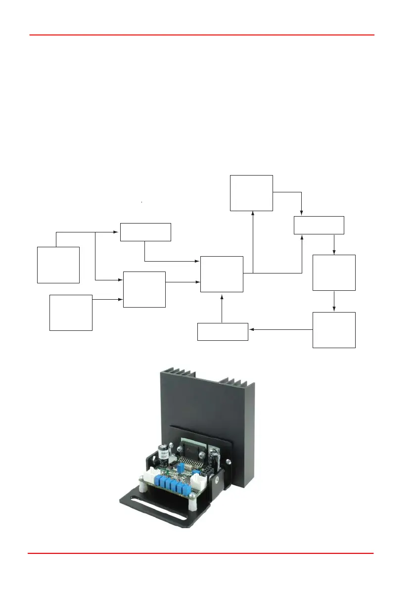
1.2.4 Servo Driver Board
The servo circuit interprets the signals from the position detector, then uses positional
error, speed and integral of current terms to output control voltages to drive the
actuator to the demanded position.
The scanner uses a non-integrating, Class 0 servo, which enables higher system
speeds compared to integrating servo systems, and is ideal for use in applications
that require vector positioning (e.g. laser marking) or raster positioning (printing or
scanning laser microscopy). It can also be used in some step and hold applications.
Furthermore, the proportional derivative circuit gives excellent dynamic performance
and includes an additional current term to ensure stability at high accelerations. The
diagram below shows the architecture of the driver in more detail.
Fig. 1.4 Servo Driver Board Schematic Diagram
Fig. 1.5 Servo Driver Circuit Board
Position
Sensing
Circuit
Command
Signal
Amplifier
Difference
Amplifier
Summing
Amplifier
Notch
Filter
Power
Amplifier
Differentiator
Jumper
position
speed
error
Current
Sensing
Circuit
Integrator
current
 Loading...