InGaAs Switchable Gain Detector Chapter 4: Operation
Rev D, April 21, 2020 Page 5
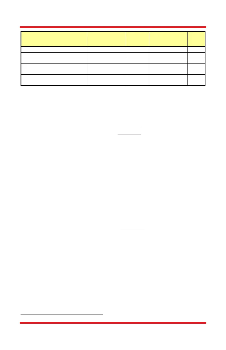
Indium Gallium Arsenide
(InGaAs)
Extended Range: Indium
Gallium Arsenide (InGaAs)
4.4. Bandwidth and Response
For the PDA detectors, the gain of the detector is dependent on the feedback
element (R
f
). The bandwidth of the detector can be calculated using the
following:
Where GBP is the amplifier gain bandwidth product and C
D
is the sum of the
photodiode junction capacitance and the amplifier capacitance.
4.5. Terminating Resistance
The maximum output of the PDA20CS2 is 10 V for high impedance loads (i.e.
R
Load
> 5 kΩ) and 5 V for 50 Ω loads. Adjust the gain so that the measured signal
level out of the PDA20CS2 is below 10 V (5 V with a 50 Ω load) to avoid
saturation.
For low terminating resistors, <5 kΩ or 1% error, an additional factor needs to be
considered. The output of the PDA includes a 50 Ω series resistor (R
s
). The
output load creates a voltage divider with the 50 Ω series resistor as follows:
Note that we already include the scale factor in our specification for the gain at
50 Ω. Refer to the table in Chapter 6 for additional performance specifications.
4.6. Gain Adjustment
The PDA20CS2 includes a low noise, low offset, high gain transimpedance
amplifier that allows gain adjustment over a 70 dB range. The gain is adjusted by
rotating the gain control knob, located on the top side of the unit. There are 8
gain positions incremented in 10 dB steps. It is important to note that the
bandwidth will decrease as the gain increases. See the specifications table on
page 7 to choose the best gain verse bandwidth for a given input signal.
Approximate values; actual wavelength values will vary.